Coupling member for damping vibrations in building structures

a technology for damping vibrations and coupling members, applied in the direction of vibration dampers, building components, shock proofing, etc., can solve the problems of shear loads in the damping system, failure modes are also considered, failure of the elements to which the damping system is connected or the vertical structural elements to which the damping element is connected, etc., to prevent the plate from sliding

Active Publication Date: 2014-11-11
CHRISTOPOULOS CONSTANTIN +1
View PDF23 Cites 25 Cited by
  • Summary
  • Abstract
  • Description
  • Claims
  • Application Information

AI Technical Summary

Benefits of technology

[0010]According to one embodiment of the invention, there is provided a building structure including a plurality of vertical elements extending from a ground surface with at least a first of the vertical elements connected to a second of the vertical elements by a coupling member, the coupling member includes a damping element for damping vibrations in the building structure resulting from relative movement between the first and second vertical elements due to lateral loads applied to the building structure. Preferably, first and second set of plates in the damping element are displaced in a vertical shear movement and act to damp vibrations in the structure via energy dissipating material resisting the displacement of the plates with respect to each other. At least one of a first and second fuse member is connected to at least one of first and second ends of the damping element respectively. The fuse member is selected from a material, and otherwise sized and dimensioned to exhibit semi-rigid behavior when the damping element undergoes deformation due to loads below a predetermined load limit and to undergo deformation when loads exceed the predetermined load limit, such that the damping element is prevented from deforming above its predefined deformation limit. First and second connecting means are also provided for rigidly connecting the first and second fuse members to the first and second vertical elements, respectively. These lateral loads result in shear loads in the damping system. Accordingly, the fuse member is designed such that the fuse is activated when a predetermined shear load in the damping element is reached.
[0022]According to another aspect of this embodiment, there is provided one or more static stiffness increasing structural members attached to a top surface of the damping element.
[0024]According to another embodiment of the invention, there is provided a method for damping vibrations caused by lateral loads being applied to a building structure including providing a damping element for damping vibrations in the building structure resulting from relative movement between the first and second vertical elements due to lateral loads applied to the building structure, the damping is caused by energy dissipating material being deformed by the first set of steel plates undergoing deformation relative to the second set of steel plates; providing at least one fuse member is connected to at least one of first and second ends of the damping element respectively; the fuse member selected from a material, and otherwise sized and dimensioned to exhibit semi-rigid behavior when the damping element undergoes deformation due to loads below a predetermined load limit and to undergo deformation when loads exceed the predetermined load limit, such that the damping element is prevented from deforming above its predefined deformation limit; and, rigidly connecting the first and second fuse members to the first and second vertical elements. These lateral loads result in shear loads in the damping system. Accordingly, the fuse member is designed such that the fuse is activated when a predetermined shear load in the damping element is reached.

Problems solved by technology

These lateral loads result in shear loads in the damping system.
Other failure modes are also contemplated, including failure of the elements to which the damping system is connected to or the vertical structural elements to which the damping element is connected.

Method used


Image

  • Coupling member for damping vibrations in building structures
  • Coupling member for damping vibrations in building structures
  • Coupling member for damping vibrations in building structures

Examples


example

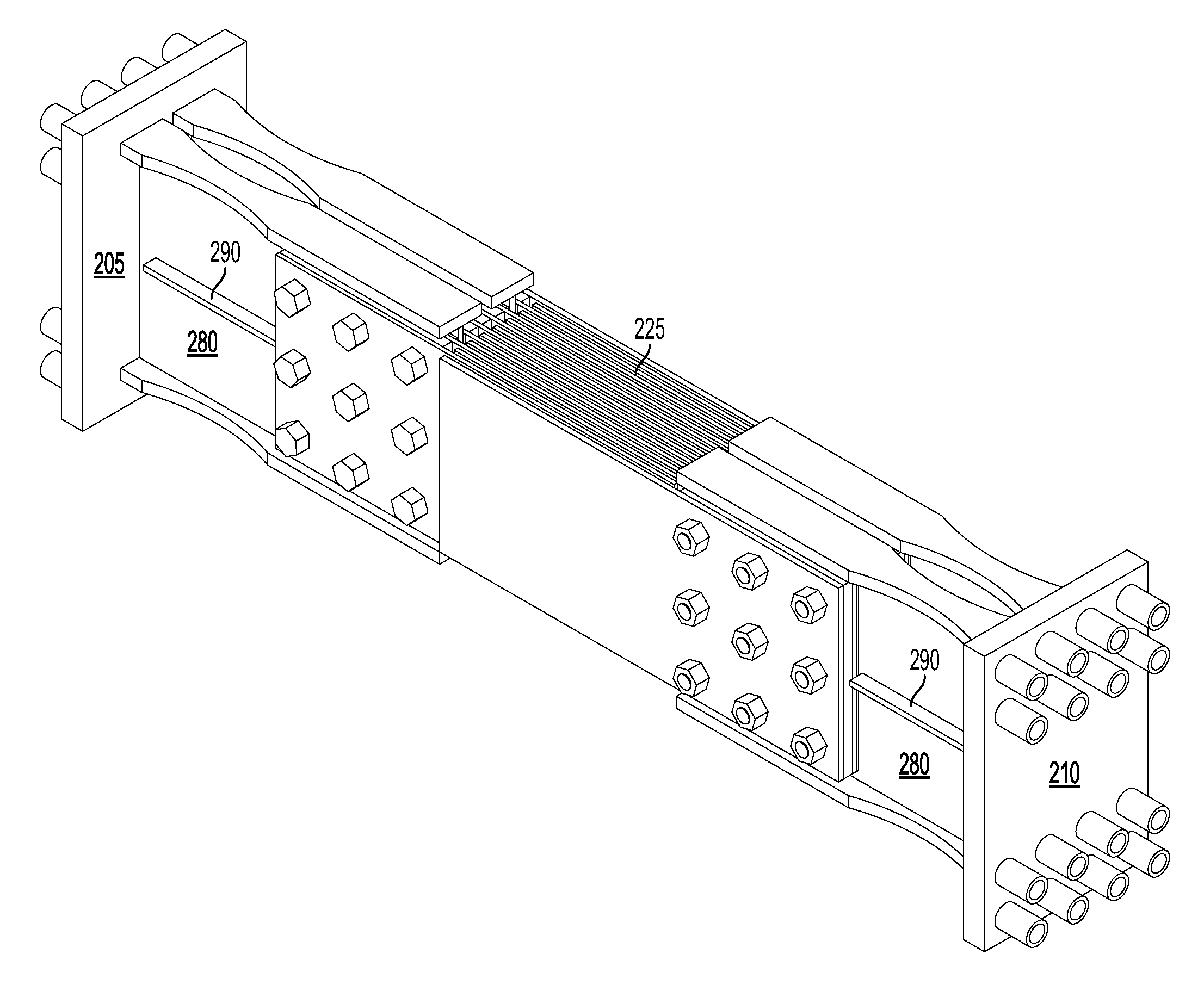
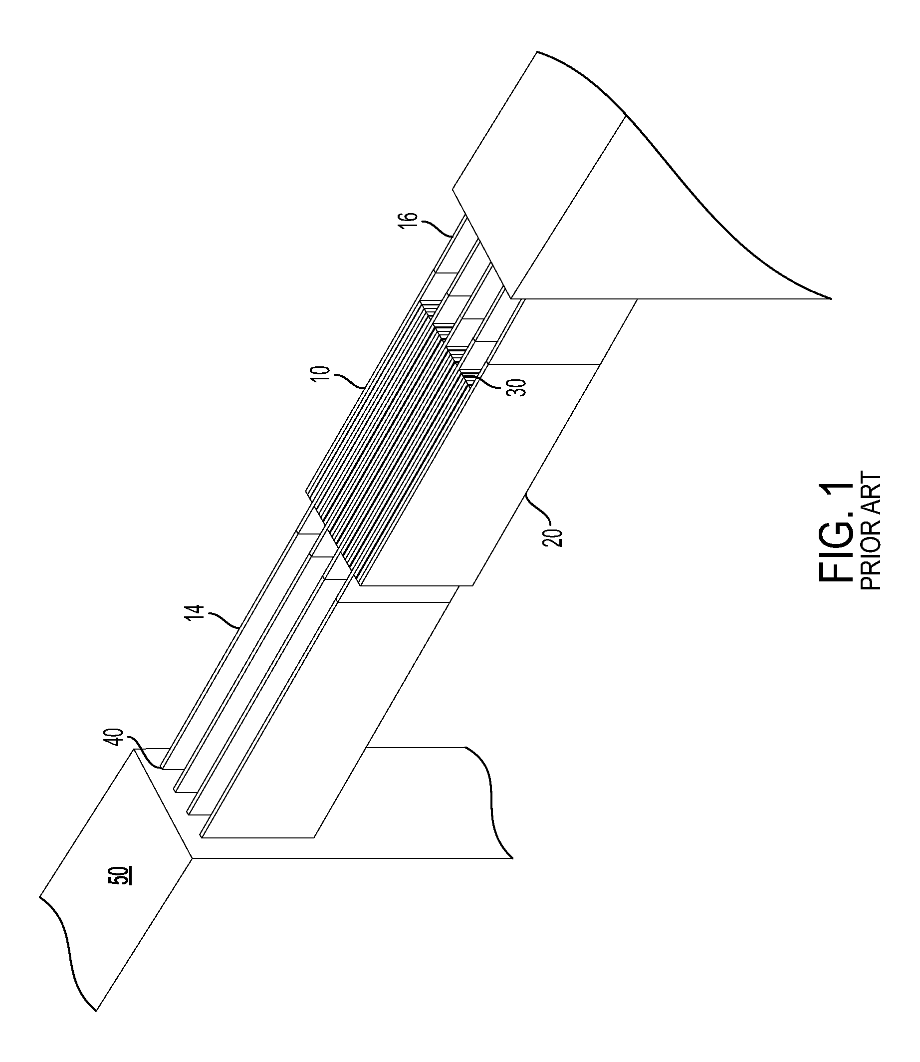
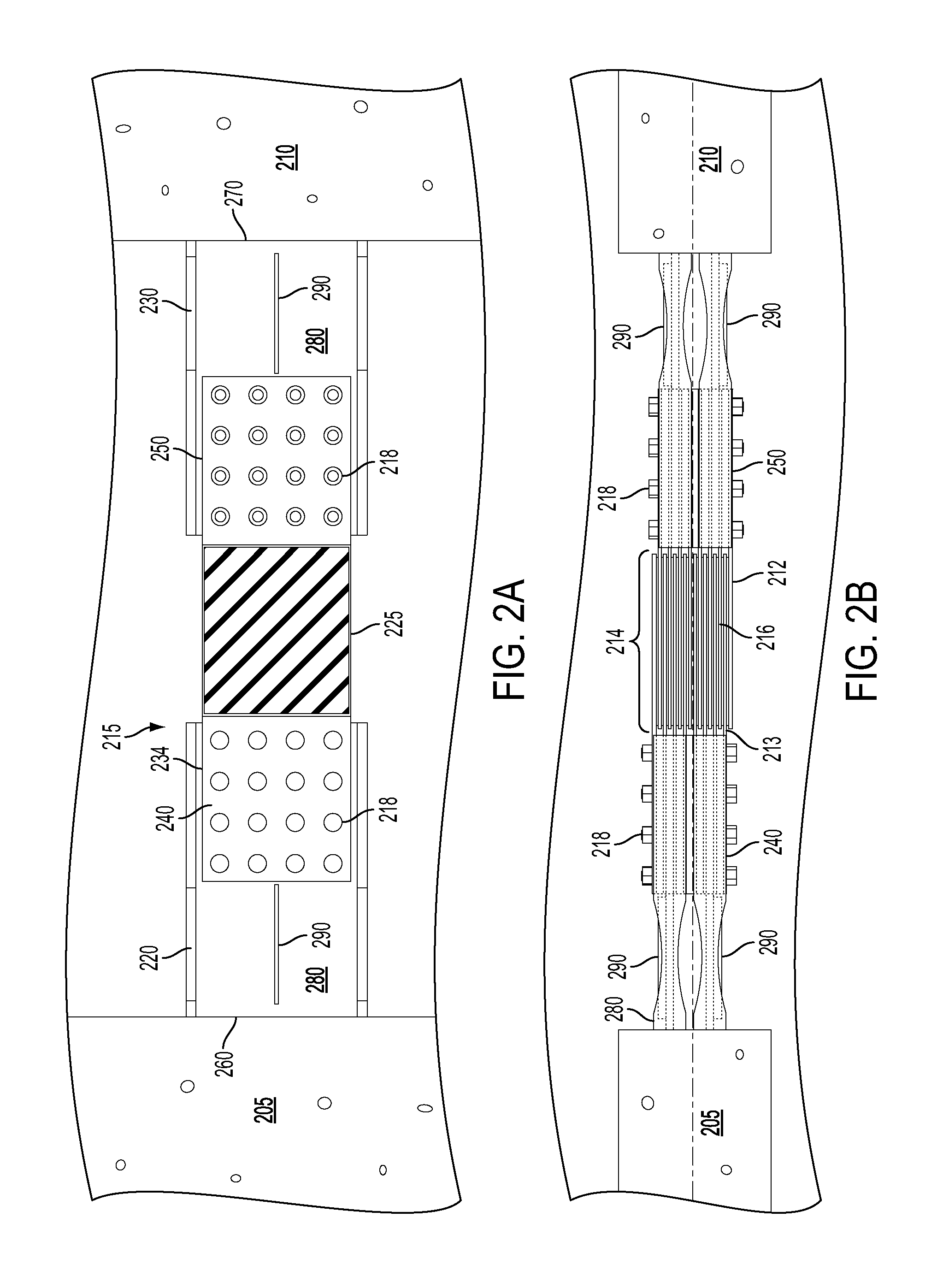
[0082]In the Example that follows, coupling members incorporating the preferred damping elements as herein described are tested as described below, with and without the fuse portion according to the invention. Further details are provided below. In the examples, reference is made to FCDs or fork configuration dampers, which refer to dampers of the type described in the preferred embodiments that incorporate two sets of a plurality of plates interdigitated with other and a damping material disposed between each pair of interdigitated plates.

[0083]Tests were conducted on two Fork Configuration Dampers (FCDs) in the laboratory at Ecole Polytechnique in Montreal. There were two different specimens tested; the first (FCD-A) was designed for inclusion in an 85-storey building and did not include a fuse portion according to the invention. The second (FCD-B) was designed for inclusion in a 50-storey building and did include a fuse portion according to the invention, such as that shown in FI...


PUM


Abstract

A building structure including a plurality of vertical elements extending from a ground surface with at least a first of the vertical elements connected to a second of the vertical elements by a coupling member, the coupling member includes a damping element for damping vibrations in the building structure resulting from relative movement between the first and second vertical elements due to lateral loads applied to the building structure. The damping element undergoes deformation due to the relative movement between the vertical elements causing the damping material to be activated in shear. At least one of a first and second fuse member is connected to at least one of first and second ends of the damping element respectively. The fuse member is selected from a material, and otherwise sized and dimensioned to exhibit semi-rigid behavior when the damping element undergoes deformation due to loads below a predetermined load limit and to undergo deformation without substantially increasing the load in the fuse and in the damping element when loads exceed the predetermined load limit, such that the damping element is prevented from deforming beyond its predetermined deformation limit and therefore avoiding any occurrence of damage that would reduce its ability to provide damping to the structure. First and second connecting means are also provided for rigidly connecting the first and second fuse members to the first and second vertical elements, respectively.

Description

[0001]This application claims priority from U.S. Provisional Application No. 61 / 432,631, filed on Jan. 14, 2011, the contents of both of which, in their entirety, are herein incorporated by reference.FIELD OF THE INVENTION[0002]The present invention relates generally to the field of building structures, and more specifically to vibration damping mechanisms for use in building structures.BACKGROUND OF THE INVENTION[0003]Modern buildings, using typical construction components such as reinforced concrete shear walls, structural steel braced frames, structural steel or reinforced concrete moment frames or combinations thereof, have low inherent damping properties which decrease with building height. Due to this low inherent damping, high-rise buildings, in particular, tend to be susceptible to excessive vibrations caused by dynamic loads. Excessive accelerations and torsional velocities can cause occupant discomfort, while excessive displacements can cause damage to non-structural and s...

Claims


Application Information

Patent Timeline
Patent Type & Authority Patents(United States)
IPC IPC(8): E04B1/98E04H9/02F16F7/00
CPCE04H9/022F16F7/003E04H9/02E04B1/98E04B1/3412F16F7/08
Inventor CHRISTOPOULOS, CONSTANTINMONTGOMERY, MICHAEL
Owner CHRISTOPOULOS CONSTANTIN
Why Eureka
Try Eureka