

Rolling cutter bit design
a cutter and rolling cutter technology, applied in cutting machines, earthwork drilling and mining, construction, etc., can solve problems such as cutter failure, deterioration of diamond table, and ultra hard layer structural failure,
- Summary
- Abstract
- Description
- Claims
- Application Information
AI Technical Summary
Benefits of technology
Problems solved by technology
Method used
Image

Examples
Embodiment Construction
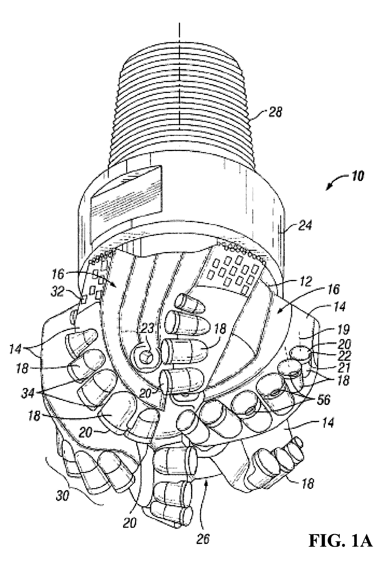
[0038]In one aspect, embodiments disclosed herein relate to bit design using rotatable cutting structures. Specifically, embodiments disclosed herein relate to improving the life of a drill bit by positioning rotatable cutting elements in particular arrangements on the drill bit.
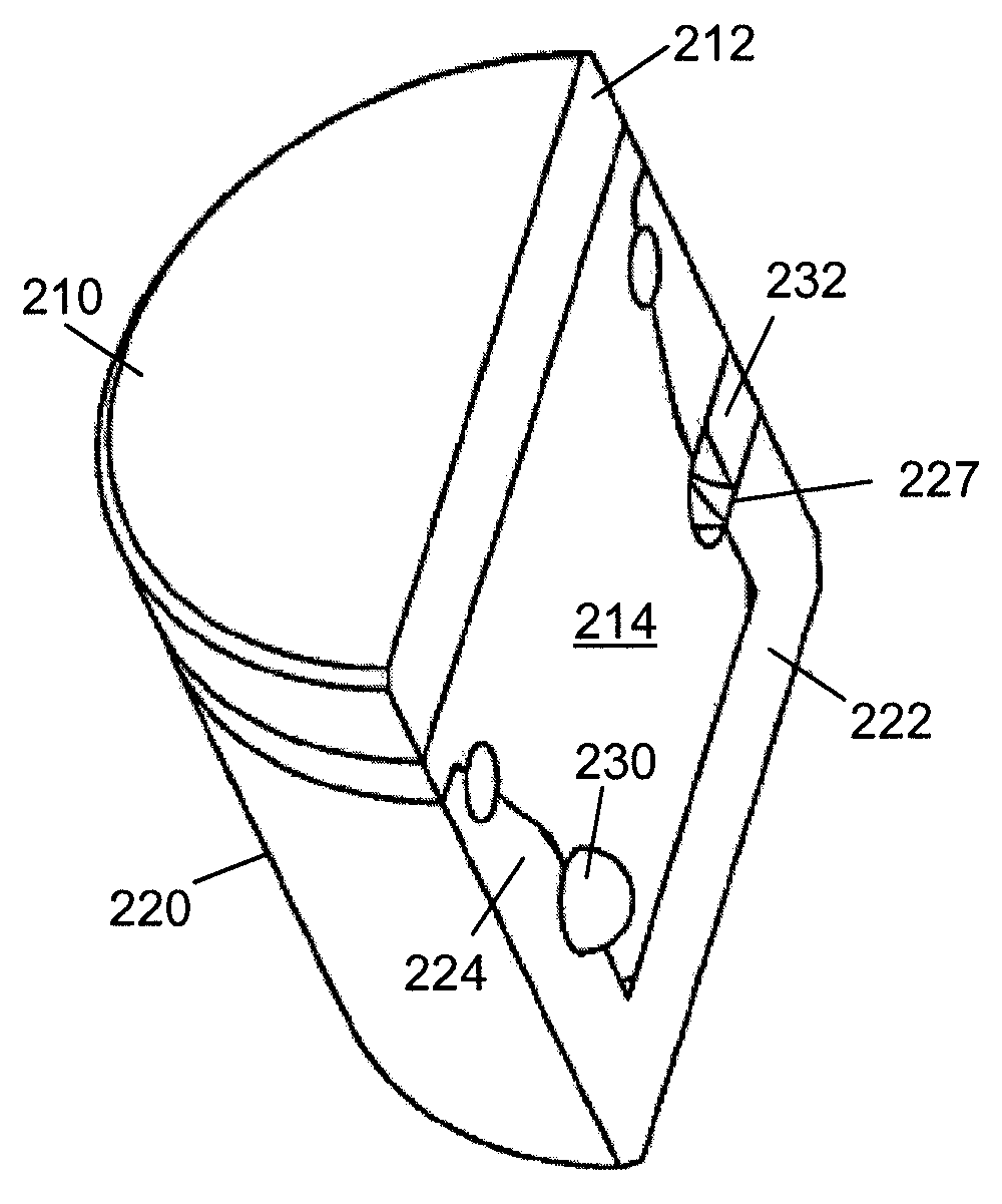
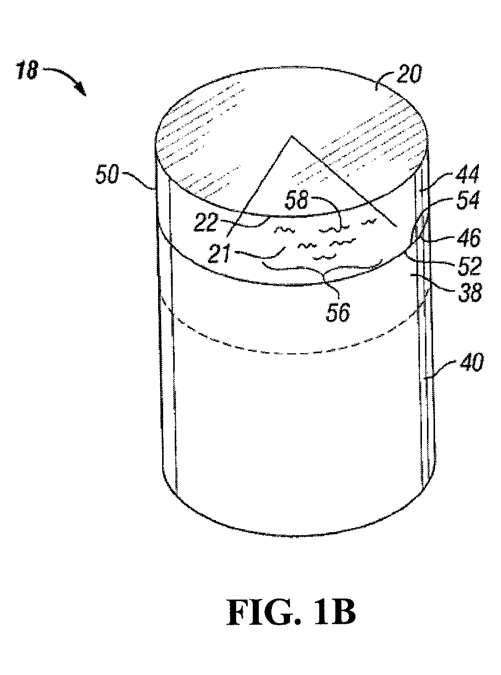
[0039]Generally, rotatable cutting elements (also referred to as rolling cutters) described herein allow at least one surface or portion of the cutting element to rotate as the cutting elements contact a formation. As the cutting element contacts the formation, the cutting action may allow portion of the cutting element to rotate around a cutting element axis extending through the cutting element. Rotation of a portion of the cutting structure may allow for a cutting surface to cut the formation using the entire outer edge of the cutting surface, rather than the same section of the outer edge, as observed in a conventional cutting element. The following discussion describes various embodiments for a rotatabl...
PUM
 Abstract
Description
Claims
Application Information