
Locking connection member of covering material and method of manufacturing covered cushion formed body

a technology of locking connection and covering material, which is applied in the direction of snap fasteners, buckles, chairs, etc., can solve the problems of difficult positioning method using a guide plate, difficult to apply to a complex curved shape, and difficulty in precisely aligning the starting end of the loop engaging elements in the engaging member holding the upholstery material to the starting end, etc., to achieve convenient and precise positioning, improve working efficiency, and easy to bend

Inactive Publication Date: 2014-11-11
KURARAY FASTENING CO LTD +1
View PDF15 Cites 15 Cited by
  • Summary
  • Abstract
  • Description
  • Claims
  • Application Information

AI Technical Summary

Benefits of technology

The present invention provides a flexible long engaging member for upholstering that is easy to position and bend along the complex curved shape of a cushion member's groove. It also provides a method for producing an upholstered cushion molding with improved working efficiency. Additionally, it offers an upholstered cushion molding.

Problems solved by technology

As described above, in case of using known engaging members holding an upholstery material, it is extremely difficult to precisely align the starting end of loop engaging elements in the engaging member holding the upholstery material to the starting end of hook engaging elements on the cushion molding.
If both the starting ends are positioned distortedly or are not in line with each other, the upholstery material is wrinkled to spoil its appearance.
The method of positioning using a guide plate is difficult to apply to a complex curved shape.

Method used


Image

  • Locking connection member of covering material and method of manufacturing covered cushion formed body
  • Locking connection member of covering material and method of manufacturing covered cushion formed body
  • Locking connection member of covering material and method of manufacturing covered cushion formed body

Examples


example 1

Production of Main Portion of Engaging Member

[0140]The following raw yarns were Raschel knitted to form a base fabric and loop engaging elements, thereby producing a main portion of engaging member.

[0141](1) Raw Yarn[0142]Chain yarn: PET finished yarn 330 T / 96 F[0143]Weft insert yarn: PET finished yarn 330T / 96F / / 2[0144]Loop yarn: PET grey yarn 167T / 30F

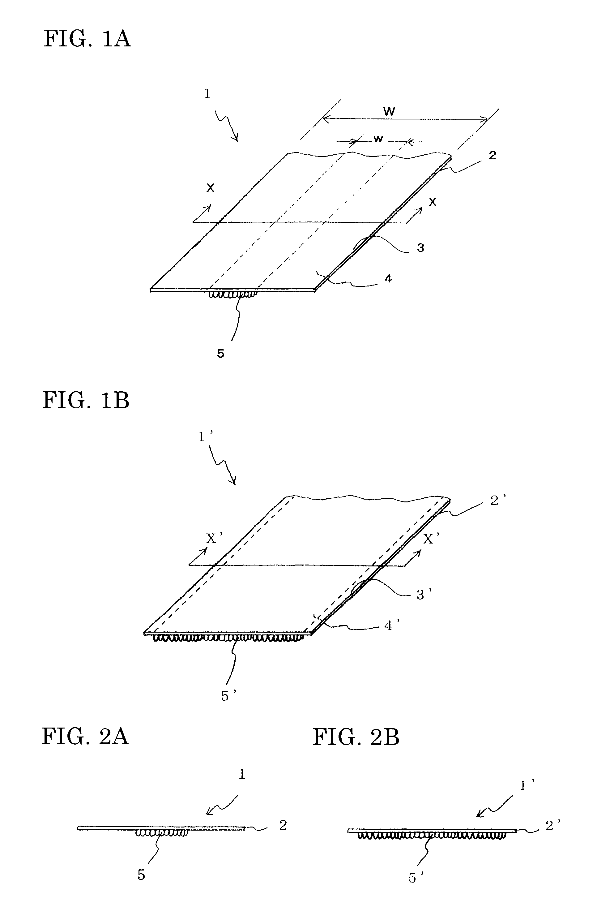
[0145](2) Knit Structure[0146]Raschel knitting: 16 in gauge[0147]Warp density: 32 course / in[0148]Loop density: 160 / in2 [0149]Loop height: 2 mm[0150]Tape width (W): 40 mm[0151]Central loop width (w): 10 mm[0152]Mass per unit area: 9 g / m2

[0153](3) Elastic Property[0154]Elongation: 4%[0155]Elastic modulus: 48%

Production of Engaging Member

[0156]The obtained main portion of engaging member is shown in FIG. 1 perspectively and in FIG. 2 cross-sectionally. On the central portion of the second main surface of the base fabric with 40 mm width, a 10 mm-wide array of loop engaging elements with a loop height of 2 mm was formed. The strip of base...

example 2

Production of Main Portion of Engaging Member Having Resin Layer

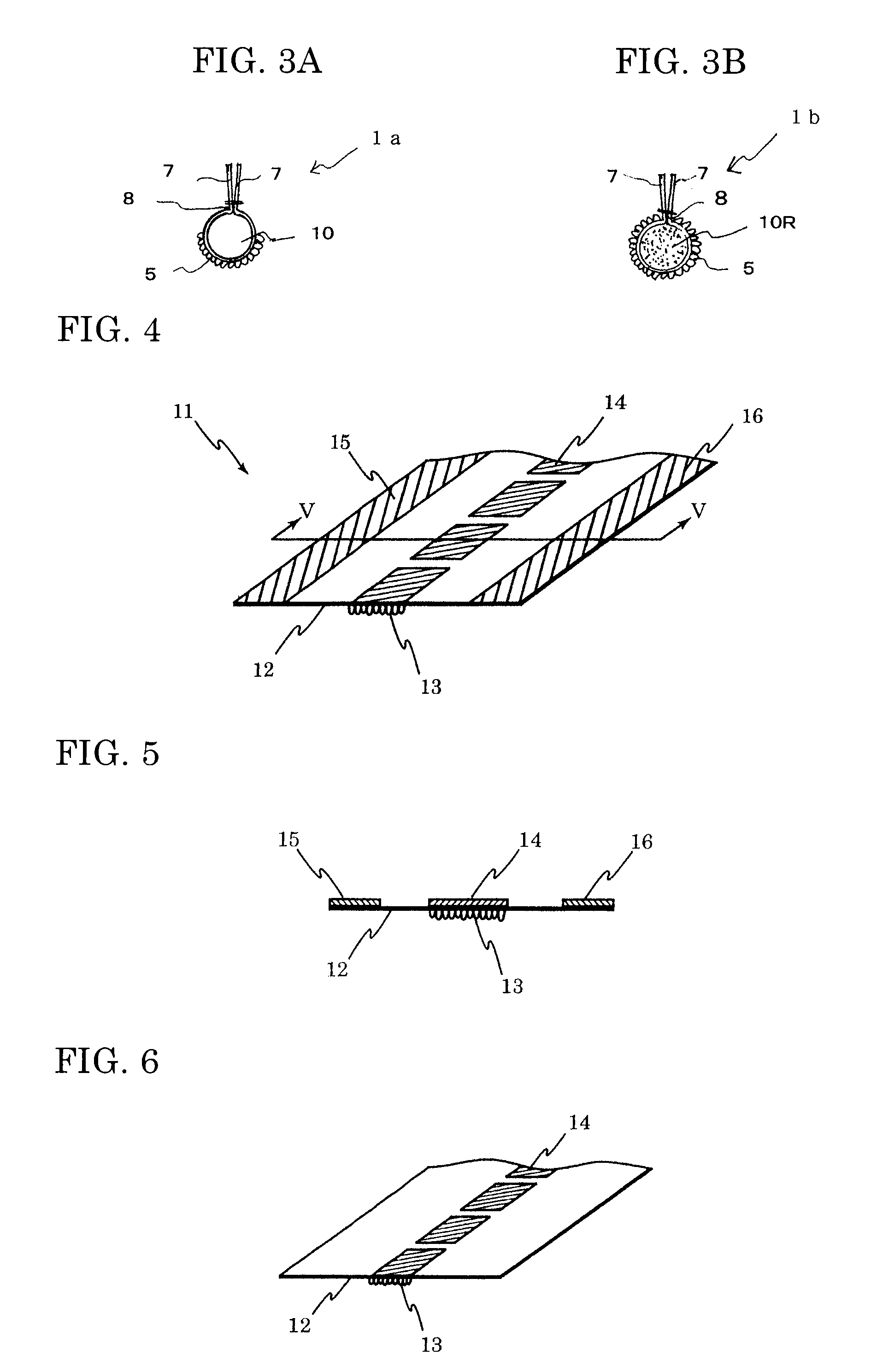
[0159]Using the same main portion of engaging member as used in Example 1, a discontinuous resin layer A was formed on the central portion of the surface (first main surface) opposite to the surface (second main surface) having the array of loop engaging elements along the lengthwise direction using a polyamide resin (“Micromelt 6211 manufactured by Henkel AG & Co.). The resin layer A had a width of 10 mm, a thickness of 120 μm and the coated portion / non-coated portion pitch was 10 mm / 5 mm. Using the same polyamide resin, a continuous resin layer B (10 mm width and 150 μm thickness) was further formed on both the edge portions as shown in FIG. 4, thereby producing the main portion of engaging member. The deflection resistance of the obtained main portion of engaging member was 60 g for the portion having the resin layer and 18 g for the portion free from the resin layer.

[0160]The resin layers B on the edge portions were...


PUM

PropertyMeasurementUnit
depthaaaaaaaaaa
heightaaaaaaaaaa
elongationaaaaaaaaaa

Abstract

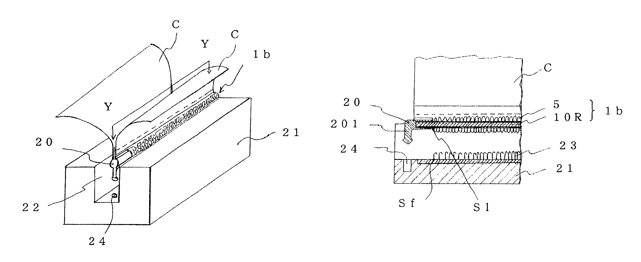
An engaging member for attaching an upholstery material to a cushion member, which has a positioning member at least one lengthwise terminal end. The positioning member places the starting end of loop engaging element portion in precise position in the groove of the cushion member. The engaging member is long and flexible and bends in conformity with the complicated shape of the curved groove. The method of producing an upholstered cushion molding using the engaging member improves the working efficiency.

Description

TECHNICAL FIELD[0001]The present invention relates to an engaging member which is used for fixing an upholstery material (covering material) on to a cushion molding (cushion member) used in the production of automotive seats, etc. The present invention further relates to a method of producing an upholstered cushion molding using the engaging member.BACKGROUND ART[0002]A method of attaching an upholstery material to a cushion molding (cushion member), which is a representative of foamed moldings, for producing an automotive seat (hereinafter may be simply referred to as “seat”) includes a hog ring method in which the metal wires embedded in both a cushion member and an upholstery material are fixed by a metal ring; an adhesive method in which a cushion member and an upholstery material are fixed by an adhesive; and a method in which a hook surface fastener made of a woven or knitted fabric or plastics is embedded in a cushion member by a mold-in process and a loop surface fastener se...

Claims


Application Information

Patent Timeline
Patent Type & Authority Patents(United States)
IPC IPC(8): B68G7/12A47C31/02B60N2/90
CPCA47C31/023B68G7/12B60N2/5825B60N2/5833B60N2/5891Y10T24/2775Y10T29/481
Inventor TAKEHARA, KEIJIONO, SATORUDOI, EIICHIROUYAMASHITA, TAKESHI
Owner KURARAY FASTENING CO LTD
Learn More