
Implantable prosthetic device for distribution of weight on amputated limb and method of use with an external prosthetic device

a prosthetic device and amputated limb technology, applied in the field of implantable prosthetic devices, can solve the problems of 25 percent of patients experiencing ulceration of the stump, use of the prosthesis, and complicated transition to use, and achieve the effects of improving the dynamic interaction, high effectiveness, and more functionality

Active Publication Date: 2014-11-11
SMITH LARRY NELSON
View PDF56 Cites 2 Cited by
  • Summary
  • Abstract
  • Description
  • Claims
  • Application Information

AI Technical Summary

Benefits of technology

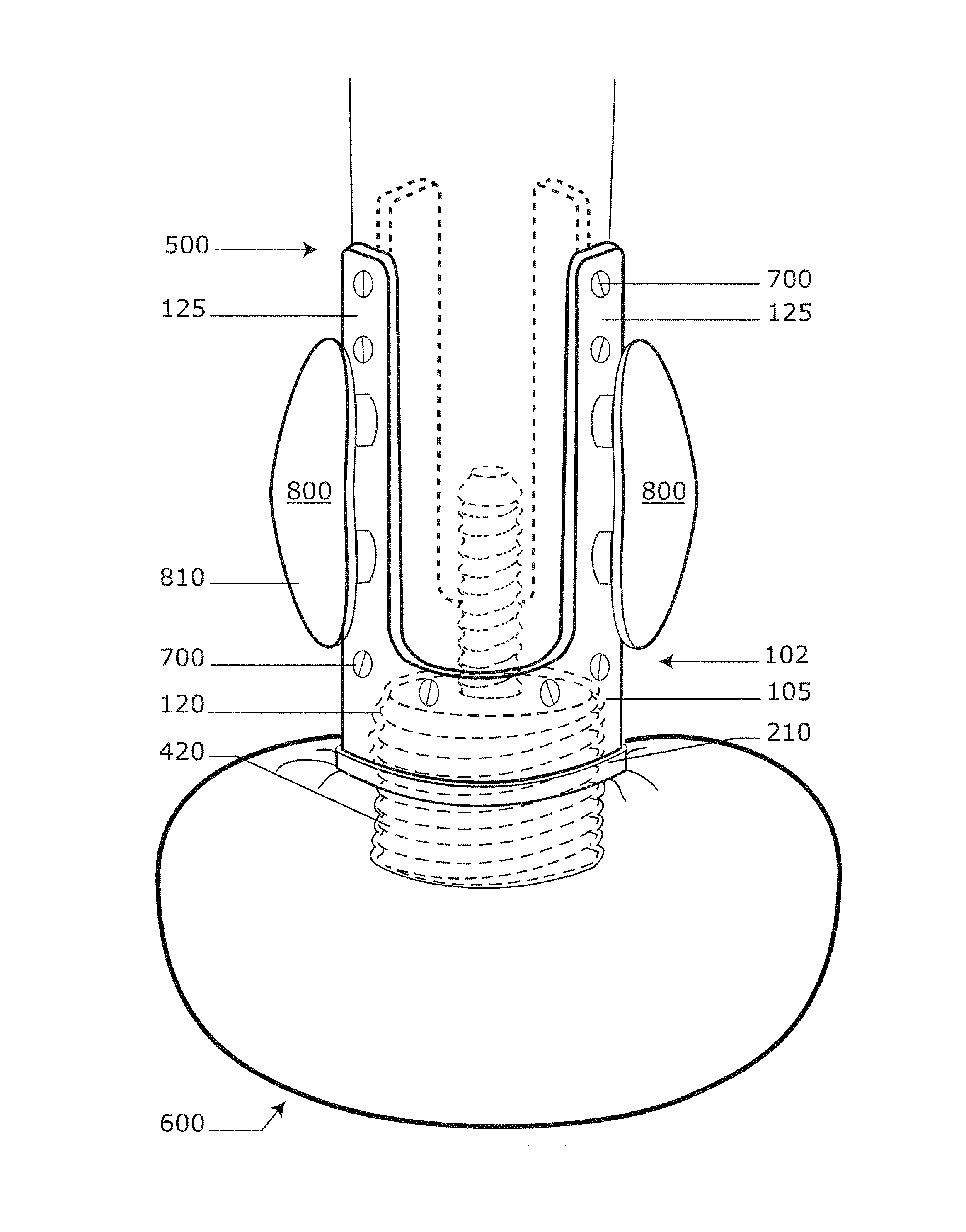
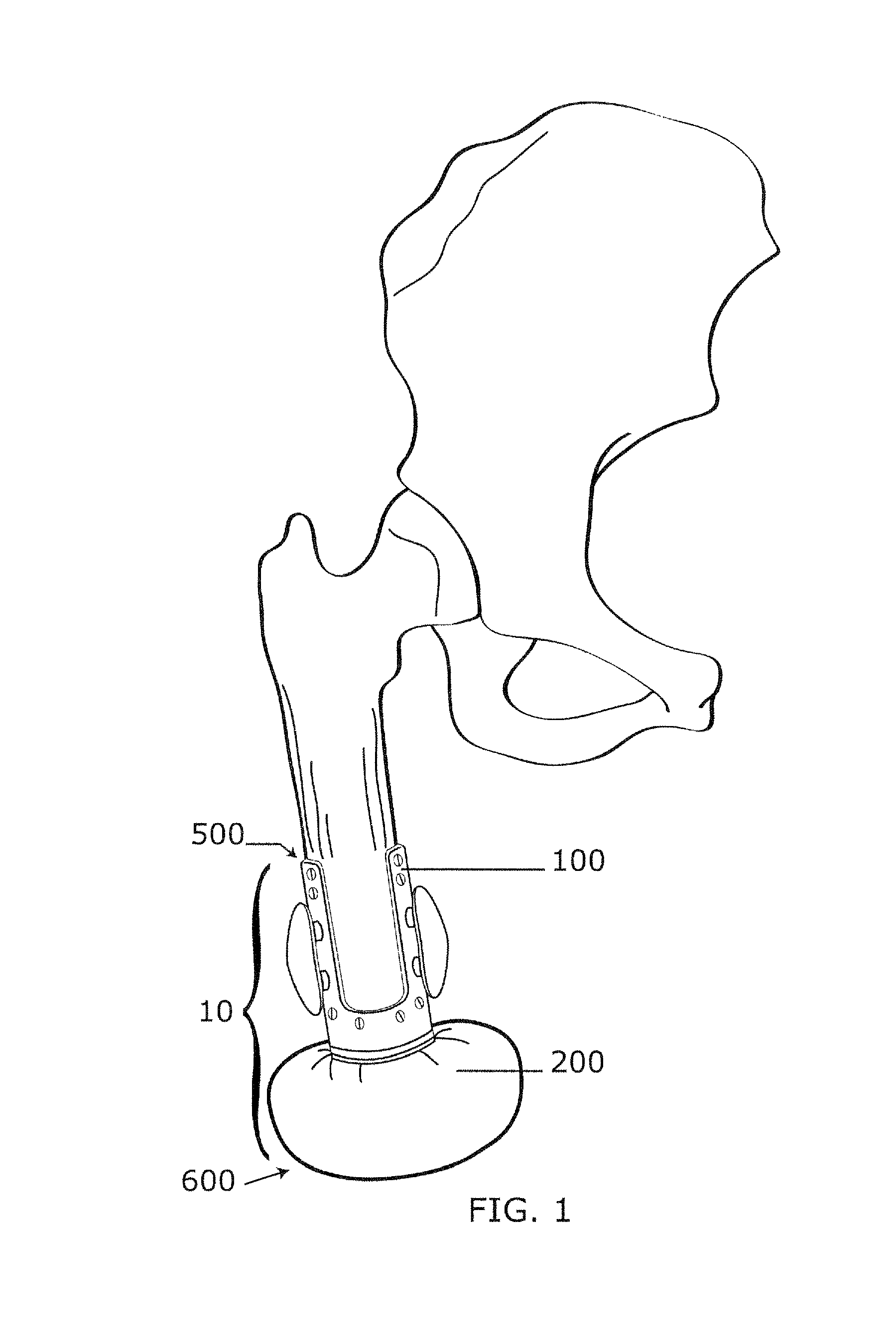
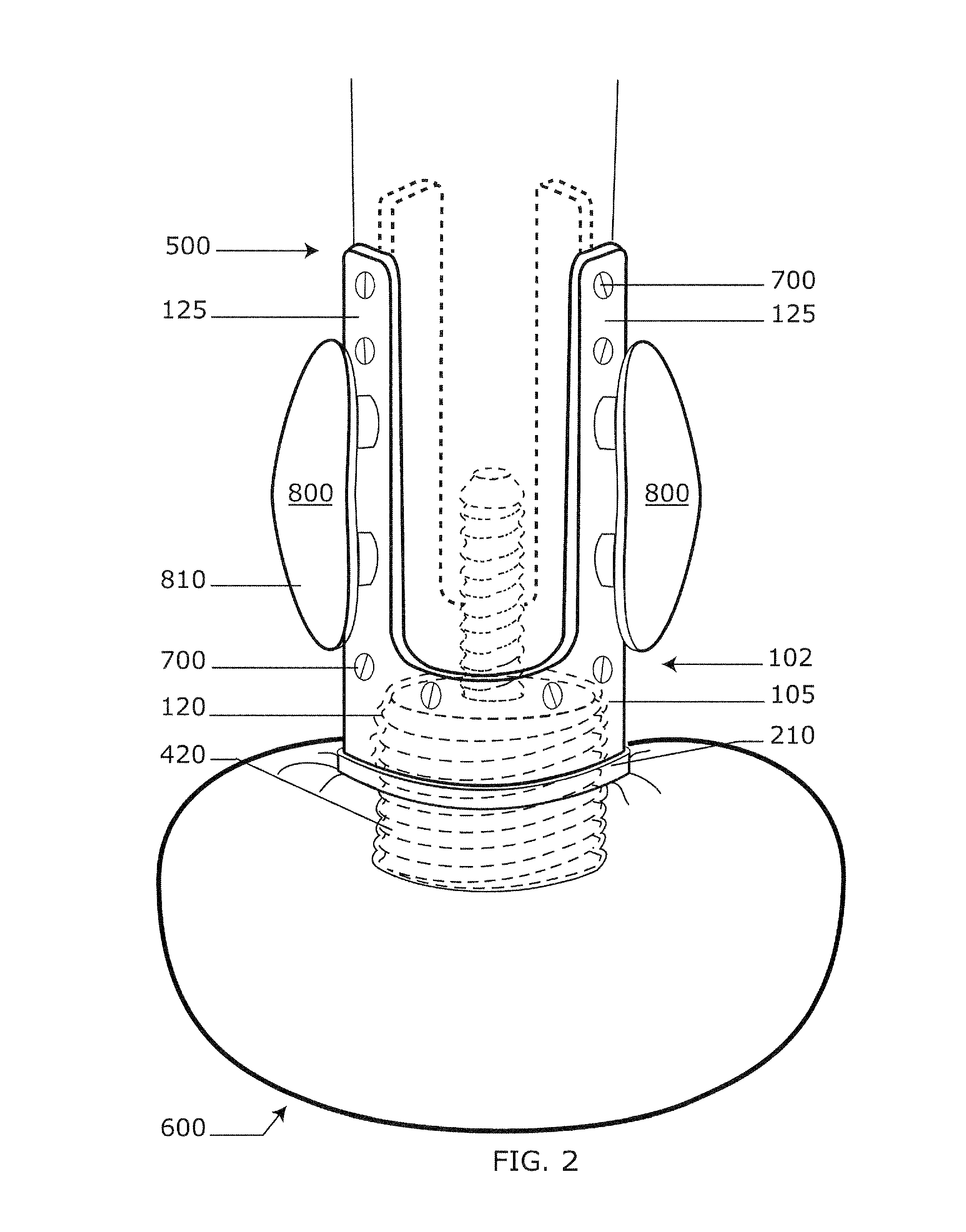
The invention provides a new prosthetic device and method for using it to improve the dynamic interaction between the reconstructed amputee residual limb and the external walking prosthesis. The device is designed to distribute the weight and force of walking over the entire surface of the residual limb, replacing the natural hydraulic system of the joints lost with the amputation. It includes an implantable force-distribution boot that acts hydraulically to accept the forces and transfer them evenly over the entire surface of the residual bone. The device also includes a plantar skin "free flap" that can be harvested and transplantated to the terminal end of the residual limb, providing a more physiologically and anatomically suited covering for the terminal end. The prosthetic limb attachment utilizes ferromagnetic materials, magnets, and an electromagnetic mechanism, which can be controlled by sensor switches that relay on-off signals to the electromagnets during the walking cycle. The device can reduce pain, tissue degradation, and skin ulcerations, allowing for longer periods of continuous use and re-integration into the work force and society.

Problems solved by technology

One of the most difficult problems that a lower extremity amputee faces today is being able to transition to the use of a new prosthesis quickly.
This delay in the use of the prosthesis is often due to the physiological changes that occur in the extremity during healing and afterwards during normal daily activities.
This transition to use is further complicated by the skin covering the stump and the boney prominences within the stump preventing comfortable and consistent use of the prosthesis because the skin covering the amputation is not physiologically or anatomically suited for the pressures involved in ambulation.
As a result, 25 percent of patients experience ulcerations of the stump and delayed wound healing from this physiological and mechanical skin mismatch on the amputee stump.
Use of the prosthetic is further limited by pain and discomfort in the stump caused by the prosthesis, with amputees receiving on average a new prosthesis every two years.3
These problems are further complicated by marked variation in the surgical amputation techniques and socket manufacturing processes, both of which are typically performed by skilled artisans.
Regardless of how advanced the prosthesis may be, if the amputee cannot use it because the stump is prepared anatomically and physiologically incorrect, then it is worthless.
With the loss of the fluid filled ankle joint in below knee amputations and the loss of the knee joint and ankle joint in above the knee amputations, the normal non-compressible fluid hydraulic system of the axial skeleton is lost.
As a result, expecting the amputee to walk on a boney stump inserted into a prosthetic socket can be unreasonable, as evidenced by the difficulty often experienced with the transition and use of a new prosthesis.
In addition to the problems of learning to walk with a prosthesis, the methods and devices used to hold the prosthesis in place on the residual limb present a whole different set of problems.
The disadvantage with most of these devices is that they are inconvenient and usually cause chafing, which leads to sores and abrasions and, in some cases, secondary skin infections.
They can also impair circulation in the residual limb causing pain and tissue degradation.
The challenge with these devices is the difficulty in attaining a permanent intact skin-prosthesis interface.
If the tissue does not heal properly around the extension, the exit wound can remain open and subject to infection and other problems.

Method used


Image

  • Implantable prosthetic device for distribution of weight on amputated limb and method of use with an external prosthetic device
  • Implantable prosthetic device for distribution of weight on amputated limb and method of use with an external prosthetic device
  • Implantable prosthetic device for distribution of weight on amputated limb and method of use with an external prosthetic device

Examples


Embodiment Construction

[0048]The subject invention in general pertains to methods and devices for providing an amputee with a prosthetic limb system for comfortable, long-term ambulation. More specifically, the subject invention pertains to one or more embodiment(s) of an implantable prosthetic component, a surgical technique for preparing the residual limb and an external prosthetic limb that works with the implantable component.

[0049]The following description will disclose that the embodiments of the subject invention are particularly useful in the field of lower extremity amputations, in particular to devices used to provide ambulation to an amputee and methods for preparing a residual limb to receive an external prosthesis. However, a person with skill in the art will be able to recognize numerous other uses that would be applicable to the devices and methods of the subject invention. While the subject application describes a use with residual leg limbs, other modifications and uses that would be appa...


PUM


Abstract

Embodiments of the invention include an implantable force distribution boot with hydraulic features that mimic the natural hydraulics of a joint. Further embodiments include an exterior prosthetic leg device having intermittent and / or variable electromagnetic features that can engage with magnetic blades on the implantable force distribution boot. In use, the exterior prosthetic leg can be maintained on a residual limb by magnetic force between the implanted blades and the exterior electromagnets. Also disclosed are surgical techniques for preparing a residual limb to better receive and adapt to a prosthetic device. The techniques include an improved surgical method for harvesting a vascularized glabrous skin free flap.

Description

BACKGROUND OF INVENTION[0001]Limb amputations have been part of humankinds' existence from its beginning as evidenced by hieroglyphics depicting techniques to fashion amputee prosthetics. Traumatic limb amputations were a common battlefield wound in the age of combat fought with swords and axes. Cautery of the residual limb or stump with hot oil or heated metal was the preferred method to stem the flow of blood on these ancient battlefields. It was not until the 1500's when Ambroise Pare demonstrated that ligation of the artery and vein with delayed or primary closure of the amputee wound provided superior healing and rehabilitation when compared to the cauterization techniques. Injury to or loss of extremities on the modern battlefield are particularly common today and is seen in 70.5 percent of all wounded soldiers. Within this group, 7.4 percent experienced amputation with explosive devices (explosive shock waves and shrapnel) accounting for 87.9 percent of the mechanism of injur...

Claims


Application Information

Patent Timeline
Patent Type & Authority Patents(United States)
IPC IPC(8): A61F2/28A61F2/76A61F2/80A61F2/70A61F2/78A61F2/30A61F2/60
CPCA61F2002/7615A61F2002/705A61F2/78A61F2002/7887A61F2/80
Inventor SMITH, LARRY, NELSON
Owner SMITH LARRY NELSON
Learn More