Refrigerating apparatus

a technology of refrigerating apparatus and compressor, which is applied in the direction of refrigeration machines, compression machines with cascade operation, gas cycle refrigeration machines, etc., can solve the problems of high temperature and pressure of refrigerant discharged from two-stage compressors, ozone layer destruction or global warming, and chlorofluorocarbons have a problem, etc., to achieve high refrigerating ability, high refrigerating ability, and efficient sucking

Active Publication Date: 2014-11-18
SANYO ELECTRIC CO LTD
View PDF31 Cites 8 Cited by
  • Summary
  • Abstract
  • Description
  • Claims
  • Application Information

AI Technical Summary

Benefits of technology

[0021]According to the first aspect of the invention, the refrigerating apparatus in which the compressor, the gas cooler, the first pressure reducing unit and the evaporator are connected to one another via the pipes and in which the natural refrigerant is used as the refrigerant comprises the second pressure reducing unit and the liquid receiver between the gas cooler and the first pressure reducing unit. The liquid receiver is connected to the suction port of the compressor via the pipe. In consequence, the pressure of the refrigerant cooled in the gas cooler is reduced by the second pressure reducing unit to expand the refrigerant, whereby the refrigerant is further cooled, and the liquefied refrigerant can be received in the liquid receiver. Therefore, the liquid refrigerant can be supplied to the evaporator. Furthermore, the gas refrigerant in the liquid receiver can efficiently be sucked from the suction port of the compressor, so that a pressure reducing effect produced by the second pressure reducing unit can be improved. Therefore, in the refrigerating apparatus in which the liquid refrigerant is efficiently received in the liquid receiver and in which the natural refrigerant is used, a high refrigerating ability can be obtained.
[0022]In the second aspect of the invention, the refrigerating apparatus in which the compressor, the gas cooler, the first pressure reducing unit and the evaporator are connected to one another via the pipes and in which the natural refrigerant is used as the refrigerant comprises the second pressure reducing unit and the liquid receiver between the gas cooler and the first pressure reducing unit, wherein the liquid receiver is connected to the intermediate pressure portion of the compressor via the pipe. In consequence, the pressure of the refrigerant cooled in the gas cooler is reduced by the second pressure reducing unit to expand the refrigerant, whereby the refrigerant is further cooled, and the liquefied refrigerant can be received in the liquid receiver. Therefore, the liquid refrigerant can be supplied to the evaporator. Furthermore, the gas refrigerant in the liquid receiver can be sucked by the intermediate pressure portion of the compressor, so that the pressure reducing effect produced by the second pressure reducing unit can be improved. Therefore, in the refrigerating apparatus in which the liquid refrigerant is efficiently received in the liquid receiver and in which the natural refrigerant is used, the high refrigerating ability can be obtained.
[0023]Moreover, in the third aspect of the invention, the refrigerating apparatus further comprises: the inner heat exchanger between the gas cooler and the second pressure reducing unit, and the outlet of the evaporator is directly connected to the suction port of the compressor via the pipe in parallel with the separate pipe which connects the outlet of the evaporator to the suction port of the compressor via the opening / closing valve and the inner heat exchanger. In consequence, when the refrigerating apparatus has a sufficient refrigerating ability, the refrigerant discharged from the gas cooler can be supercooled by the low-temperature low-pressure refrigerant discharged from the evaporator. Furthermore, the refrigerating ability in the evaporator is sufficiently secured, whereby a temperature difference between the high-temperature refrigerant and the low-temperature refrigerant can be increased in the inner heat exchanger. Therefore, a heat exchange efficiency can be improved.
[0024]Furthermore, in the fourth aspect of the invention, the intermediate portion between the heat exchanger and the second pressure reducing unit is connected to the intermediate portion between the liquid receiver and the first pressure reducing unit via the opening / closing valve and the pipe, whereby the refrigerant can be supplied to the first pressure reducing unit without circulating the refrigerant through the second pressure reducing unit and the liquid receiver. In consequence, when the refrigerant is sufficiently condensed in the gas cooler and the inner heat exchanger, the refrigerant is not expanded in the second pressure reducing unit and the liquid receiver, and the condensed refrigerant is directly fed into the evaporator, whereby the refrigerating efficiency of the refrigerating apparatus can be improved.
[0025]In addition, according to the fifth aspect of the invention, the opening / closing degree of the second pressure reducing unit is controlled in accordance with the suction-side pressure of the compressor, whereby the amount of the refrigerant to be received in the liquid receiver and the flow rate into the compressor can be controlled. Therefore, when the refrigerant gathers on the high pressure side of the compressor, the rise of the pressure can be prevented.
[0026]Moreover, in the sixth aspect of the invention, the opening / closing degree of the second pressure reducing unit is controlled in accordance with the pressure difference between the discharge-side pressure of the compressor and the suction-side pressure thereof, whereby the amount of the refrigerant to be received in the liquid receiver and the flow rate into the compressor can be controlled. Therefore, when the refrigerant gathers on the high pressure side of the compressor, the rise of the pressure can be prevented. It is to be noted that the second pressure reducing unit is controlled so as to obtain a constant difference between the pressures before and after the compressor. Therefore, a substantially constant difference between the pressures before and after the first expansion valve is obtained, and the operation of the first pressure reducing unit can be stabilized. In consequence, the refrigerating ability of the refrigerating apparatus can be stabilized.

Problems solved by technology

Heretofore, a chlorofluorocarbon-based refrigerant has been used in a refrigerating apparatus, but chlorofluorocarbon has a problem such as ozone layer destruction or global warming.
However, the refrigerant discharged from the two-stage compressor 11 has very high temperature and pressure.
However, there occurs a problem that a large amount of liquefied excessive refrigerant is generated in the refrigerating apparatus in a case where the refrigerating apparatus is sufficiently cooled.

Method used


Image

  • Refrigerating apparatus
  • Refrigerating apparatus
  • Refrigerating apparatus

Examples


embodiment 1

(1) Refrigerating Apparatus to which the Present Invention is Applied

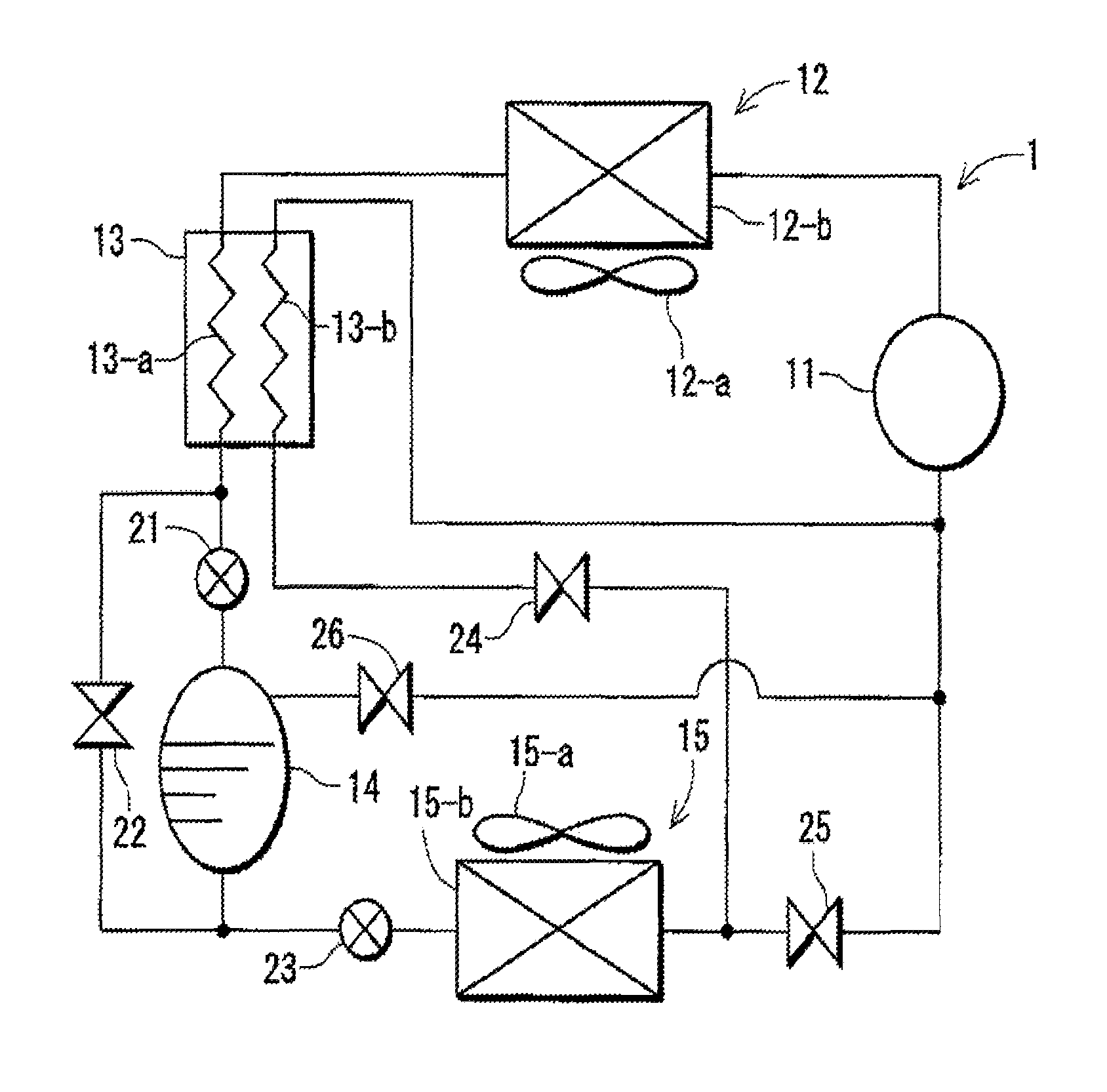
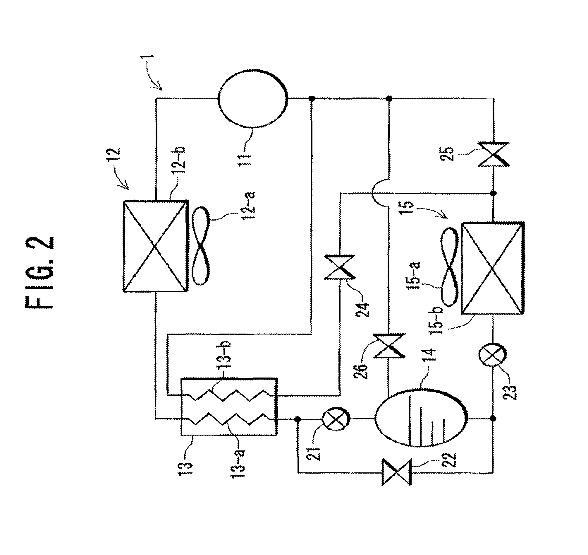
[0039]FIG. 2 shows a refrigerant circuit 1 of a refrigerating apparatus according to one embodiment to which the present invention is applied. In the drawing, reference numeral 11 is a compressor, 12 is a gas cooler, 13 is a cascade heat exchanger (an inner heat exchanger), 14 is a liquid receiver, 15 is an evaporator, 21 is a second expansion valve (a pressure reducing unit), 22, 24, 25 and 26 are electromagnetic valves (opening / closing valves), and 23 is a first expansion valve.

[0040]It is to be noted that the compressor 11 is a multistage compressor of a single stage or two or more stages. A refrigerant has a sub-critical state on the low pressure side of this compressor 11, and the discharged refrigerant has a supercritical state, so that the whole refrigerating apparatus has a trans-critical state. As one example of the refrigerant having such properties, carbon dioxide is used in the present embodiment.

[0041]...

embodiment 2

[0065]Next, another embodiment of the present invention will be described in detail with reference to FIGS. 7 to 11.

(5) Refrigerating Apparatus to which the Present Invention is Applied

[0066]FIG. 7 shows a refrigerant circuit 1 of a refrigerating apparatus according to another embodiment to which the present invention is applied. In the drawing, reference numeral 11 is a compressor, 12 is a gas cooler, 13 is a cascade heat exchanger (an inner heat exchanger), 14 is a liquid receiver, 15 is an evaporator, 21 is a second expansion valve (a pressure reducing unit), 22, 24, and 26 are electromagnetic valves (opening / closing valves), and 23 is a first expansion valve.

[0067]It is to be noted that the compressor 11 is a multistage compressor of two or more stages in which a refrigerant can be sucked not only from a low pressure portion but also from an intermediate pressure portion. The refrigerant has a sub-critical state on the low pressure side of this compressor 11, and the discharged ...


PUM


Abstract

A refrigerating circuit in which a compressor, a gas cooler, a first pressure reducing unit and an evaporator are successively annularly connected to one another via pipes includes a second pressure reducing unit and a liquid receiver between the gas cooler and the first pressure reducing unit, and the liquid receiver is connected to the suction port of the compressor via a pipe. Then, the opening / closing degree of the second pressure reducing unit is controlled in accordance with a pressure difference between the discharge-side pressure of the compressor and the suction-side pressure thereof, whereby the amount of the refrigerant to be circulated is increased when the refrigerating ability runs short, and the excessive refrigerant is received in the liquid receiver when the refrigerating ability becomes excessive, so that the amount of the refrigerant to be circulated can be adjusted.

Description

BACKGROUND OF THE INVENTION[0001]1. Field of the Invention[0002]The present invention relates to a refrigerating apparatus which includes a refrigerant circuit constituted by connecting a compressor, a gas cooler, a pressure reducing unit, an evaporator and the like via pipes and in which a natural refrigerant such as carbon dioxide (CO2) is used with a supercritical pressure as the discharge-side pressure of the compressor.[0003]2. Description of the Related Art[0004]Heretofore, a chlorofluorocarbon-based refrigerant has been used in a refrigerating apparatus, but chlorofluorocarbon has a problem such as ozone layer destruction or global warming. Therefore, the use of chlorofluorocarbon has started to be strictly regulated, and the development of a refrigerating apparatus has been advanced in which a natural refrigerant such as CO2 or hydrocarbon is used as a substitute refrigerant.[0005]In particular, CO2 is the natural refrigerant having a small global warming coefficient, and is...

Claims


Application Information

Patent Timeline
Patent Type & Authority Patents(United States)
IPC IPC(8): F25B40/00F25B1/00F25B9/00
CPCF25B2309/061F25B2400/23F25B2400/0409F25B9/008F25B2600/2513F25B2400/04F25B1/00F25B2400/13F25B40/00F25B43/00
Inventor MIHARA, KAZUHIKO
Owner SANYO ELECTRIC CO LTD
Why Eureka
Try Eureka