Kite ground station and system using same

a technology of ground station and kite, which is applied in the direction of electric generator control, machines/engines, transportation and packaging, etc., can solve the problems of kite take-off and landing, and achieve the effect of facilitating take-off and landing

Inactive Publication Date: 2014-11-18
MAKANI TECH LLC
View PDF44 Cites 27 Cited by
  • Summary
  • Abstract
  • Description
  • Claims
  • Application Information

AI Technical Summary

Problems solved by technology

However, take-off and landing of such kites can present difficulties, as the kites may not be well adapted for landings similar to that of an aircraft.

Method used


Image

  • Kite ground station and system using same
  • Kite ground station and system using same
  • Kite ground station and system using same

Examples


Embodiment Construction

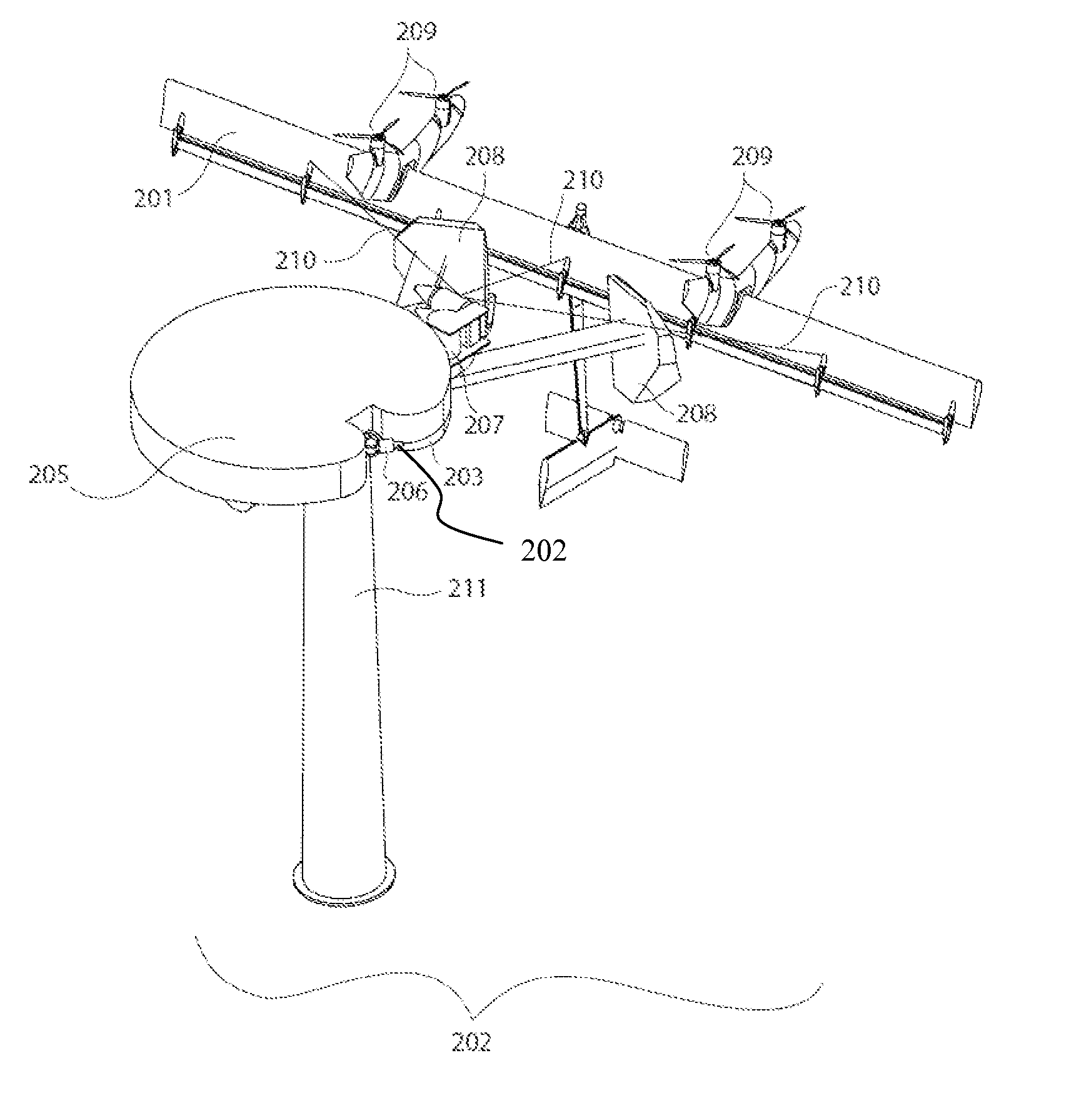
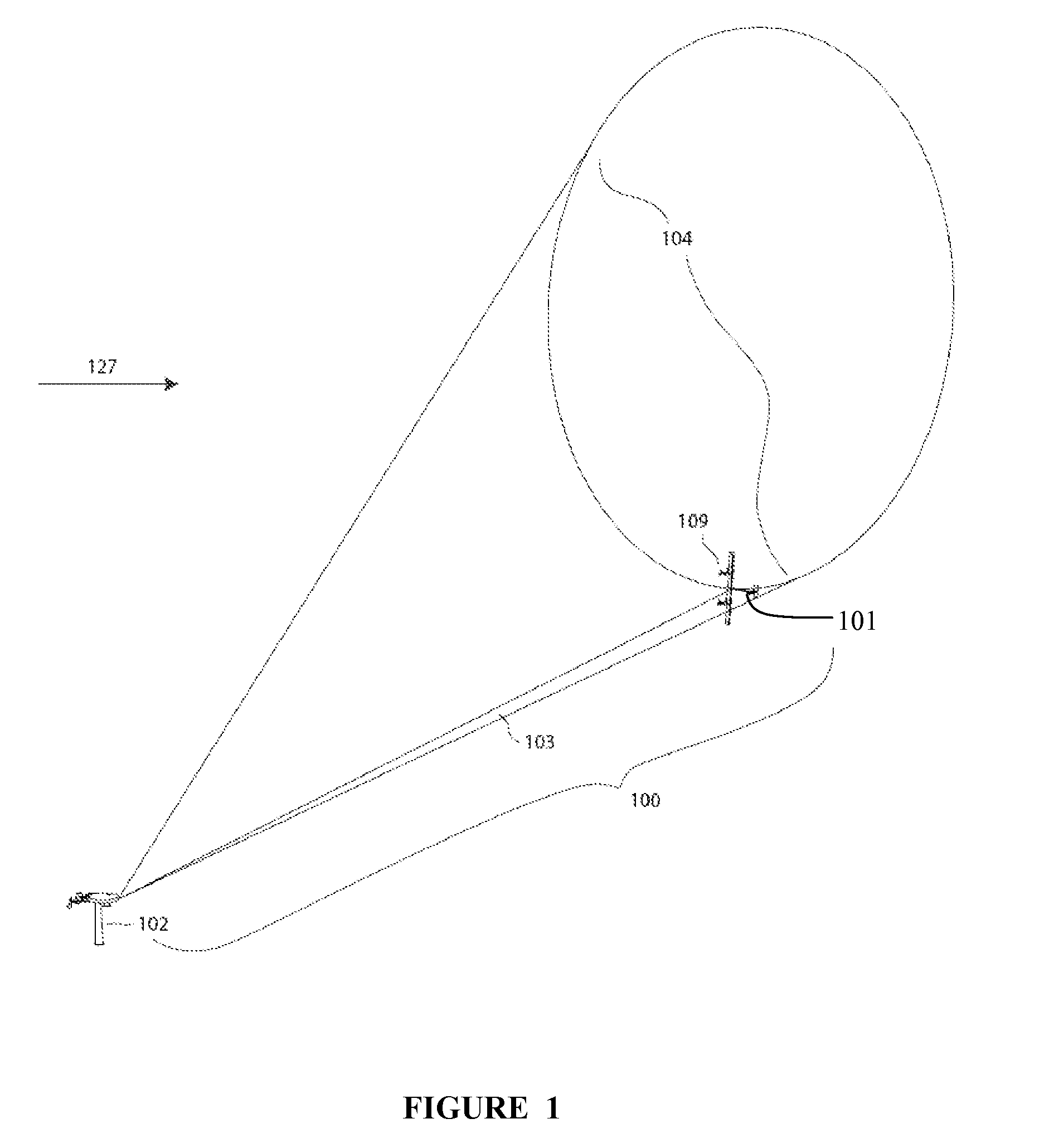
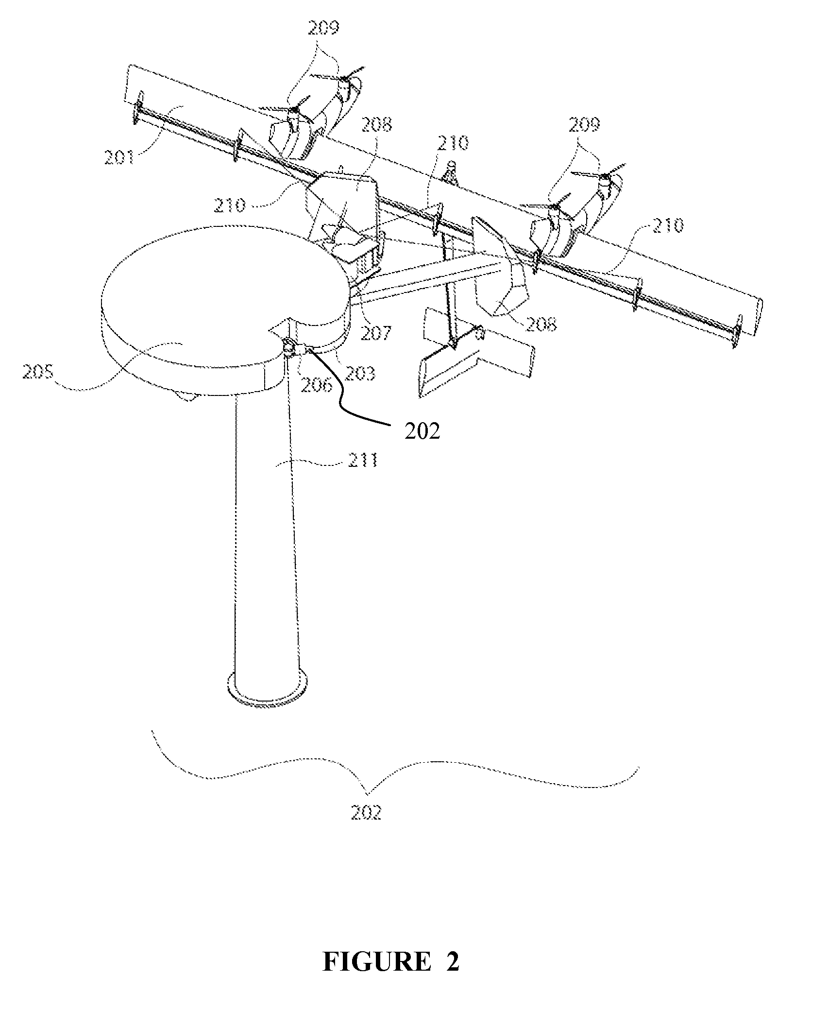
[0017]A kite system incorporating a ground station for launching and landing the kite is disclosed. Kite systems incorporating rotors on the kite are being developed for numerous purposes, including for the generation of power, use as traction or motive devices, and use for surveillance or observation. Some kite systems are designed to generate power by flying a crosswind flight path, using the onboard rotors to generate power using onboard electrical generators. Generated power is then sent down the tether and fed into batteries or the grid. To launch and land, the kite system uses power applied to the onboard rotors to provide static thrust with the onboard rotors, hovering the kite.

[0018]To support the landing of a tethered craft, the tether is reeled in on a winch which is attached to a freely-pivoting perch base. As the winch turns, it causes the freely pivoting base to turn in an opposite orientation until the tether engages a levelwind adapted to evenly wind the tether onto t...


PUM


Abstract

A kite system with a ground station adapted for airborne power generation. The kite system may include a kite which includes one or more airfoils which have mounted thereon a plurality of turbine driven generators. The turbine driven generators may also function as motor driven propellers in a powered flight mode, which may be used during take-off, which may include aspects of vertical take-off and landing. A perch adapted to facilitate the take-off and landing may be used as part of the system. The perch may pivot such that the pivot is oriented towards the tension direction of the tether.

Description

CROSS-REFERENCE TO RELATED APPLICATIONS[0001]This application claims priority to U.S. Provisional Patent Application No. 61 / 577,039 to Vander Lind, filed Dec. 18, 2011, which is hereby incorporated by reference in its entirety.STATEMENT REGARDING FEDERALLY SPONSORED RESEARCH OR DEVELOPMENT[0002]This invention was made with government support under Contract Numbers DE-AR0000122 / AR0000243 awarded by Advanced Research Projects Agency-Energy (ARPA-E). The government has certain rights in the invention.BACKGROUND[0003]1. Field of the Invention[0004]The present invention relates to a system and method of flying and perching tethered flying vehicles.[0005]2. Description of Related Art[0006]Crosswind kite systems comprising tethered wings (kites) can extract useful power from the wind for purposes such as, for example, generating electricity, lifting or towing objects or vehicles, etc. To provide or use consistent power, it may be desired to fly the kite in repeating trajectories (i.e., a l...

Claims


Application Information

Patent Timeline
Patent Type & Authority Patents(United States)
IPC IPC(8): F03D11/04B64F3/00B64C31/06F03D5/04
CPCF03D11/04F03D5/04Y02E10/728F05B2240/917B64C31/06Y02E10/70Y02E10/725B64F3/00F05B2240/921B64C39/022B64F1/12F03D9/002F03D13/20F03D9/25F03D1/02F03D13/22F03D9/30Y02E10/72F03D9/32
Inventor VANDER, LIND, DAMON
Owner MAKANI TECH LLC
Why Eureka
Try Eureka