Protection circuit, battery pack and charging system

a technology of protection circuit and rechargeable battery, which is applied in the direction of safety/protection circuit, secondary cell servicing/maintenance, cell components, etc., can solve the problems of increasing the temperature of the battery pack, insufficient heat generated by the heater, and the inability to use the battery pack permanently. , to achieve the effect of reducing the occasions of discharging the rechargeable battery

Active Publication Date: 2014-11-18
PANASONIC CORP
View PDF10 Cites 16 Cited by
  • Summary
  • Abstract
  • Description
  • Claims
  • Application Information

AI Technical Summary

Benefits of technology

[0009]Thus, an object of this invention is to provide a protection circuit of a rechargeable battery capable of reducing the occasions of discharging the rechargeable battery upon melting the temperature fuse, as well as a battery pack and a charging system having such a protection circuit.

Problems solved by technology

When this kind of battery pack detects an abnormality of the rechargeable battery, it causes a heater to generate heat based on the output voltage of the rechargeable battery to melt the temperature fuses so that the battery pack can no longer be used on a permanent basis.
Nevertheless, if the battery voltage of the rechargeable battery is low, there are cases where the amount of heat generated by the heater is insufficient even if the battery voltage is applied to the heater, whereby the temperature fuses will not melt.
In the foregoing case, in addition to the temperature fuses not melting, there is also a drawback in that the heater within the battery pack will continue to generate heat and cause the temperature of the battery pack to increase.
Nevertheless, since the technology described in Patent Document 1 melts the temperature fuses by discharging the rechargeable battery when there is an abnormality that may melt the fuses, there is a drawback in that this is undesirable from the perspective of safety.

Method used


Image

  • Protection circuit, battery pack and charging system
  • Protection circuit, battery pack and charging system
  • Protection circuit, battery pack and charging system

Examples


first embodiment

[0020](First Embodiment)

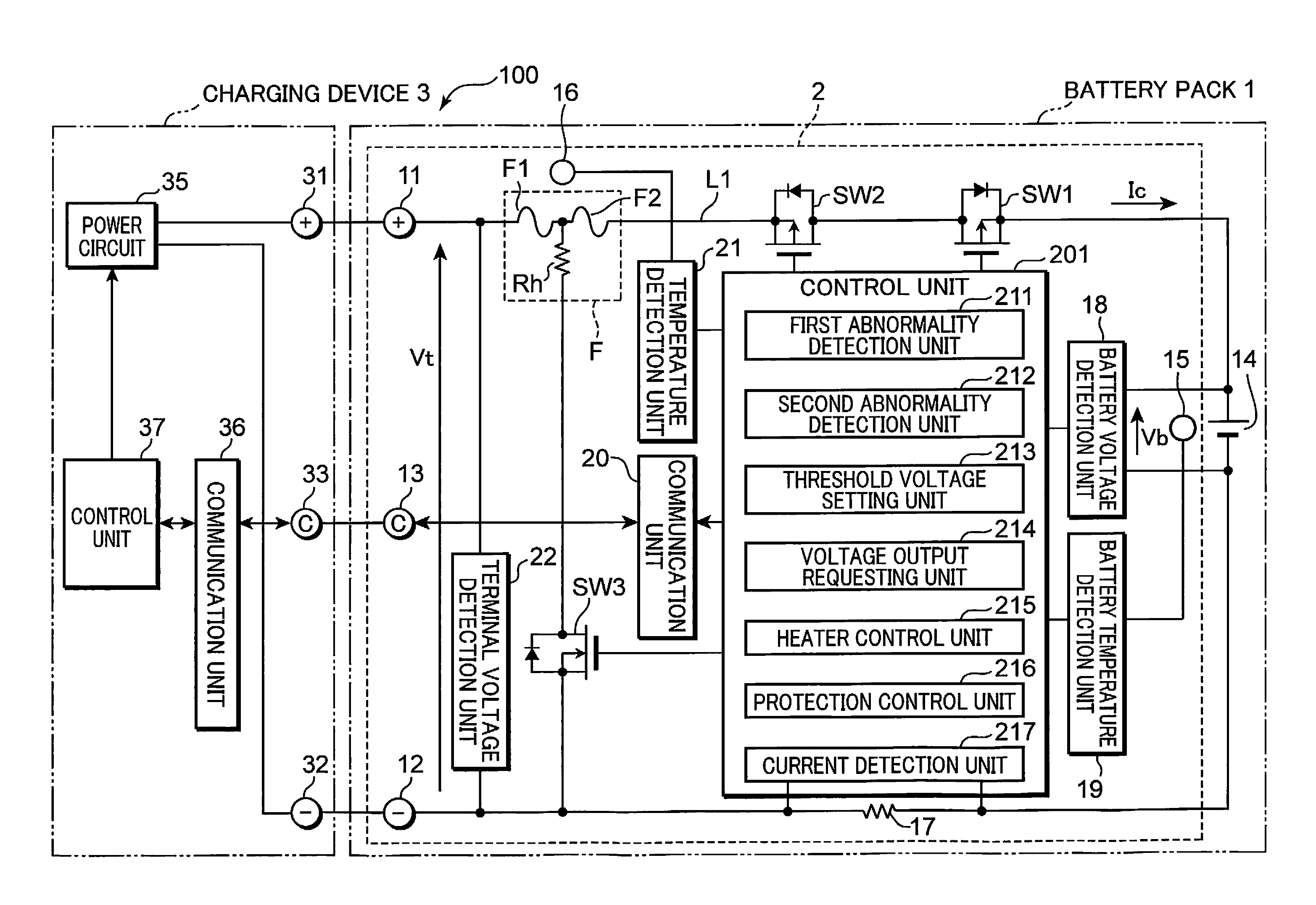
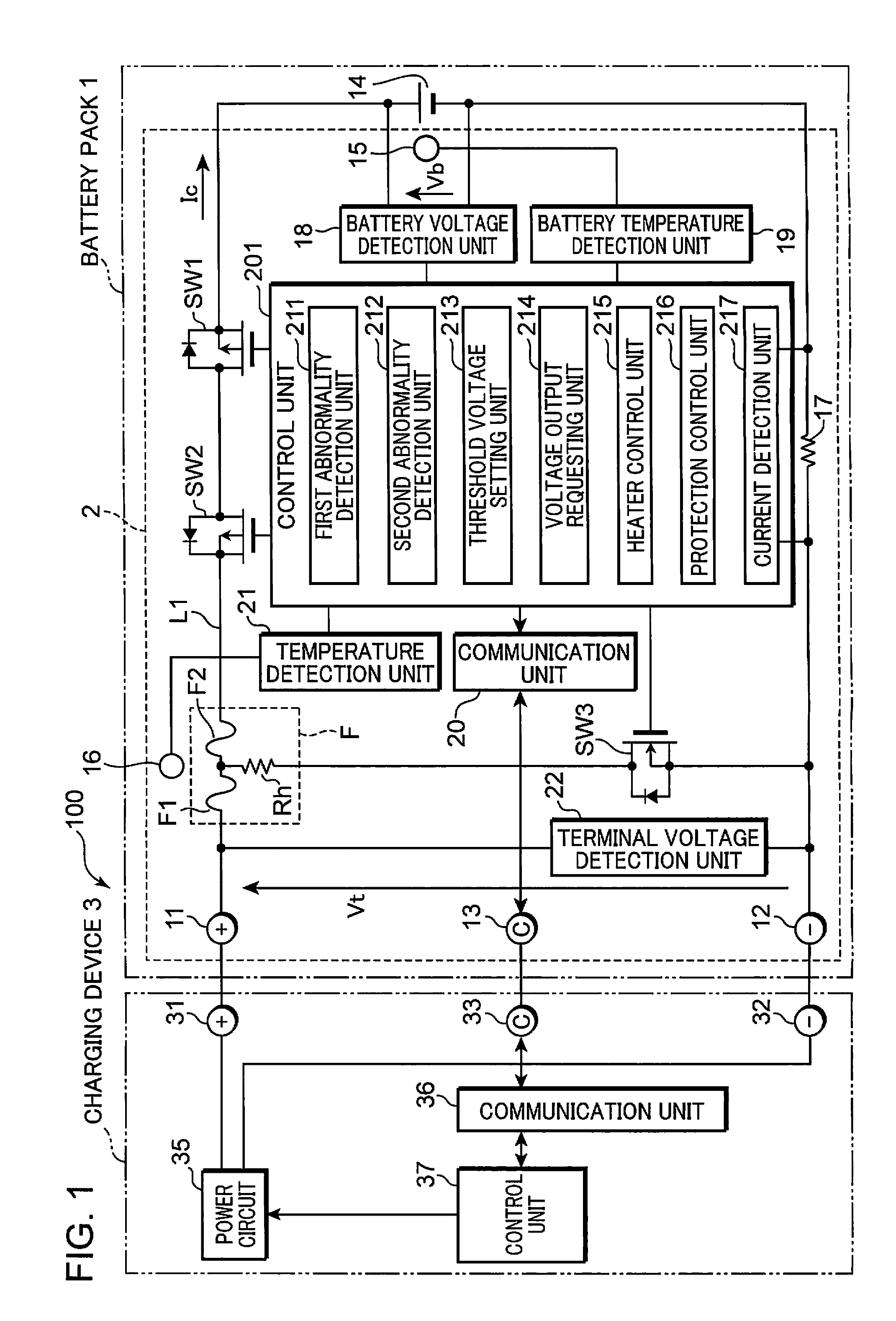
[0021]FIG. 1 is a block diagram showing an example of the configuration of a battery pack1 having a protection circuit 2 and a charging system 100 according to the first embodiment of the present invention.

[0022]The charging system 100 is configured by the battery pack 1 and the charging device 3 (charging unit) being connected. Note that the charging device 3 may be built into, for example, a battery-mounted device of various electronic devices such as portable personal computers, digital cameras and cell phones, and vehicles such as electrical vehicles and hybrid cars, and the charging system 100 may be configured as the foregoing battery-mounted device.

[0023]The charging device 3 may be, for example, a power circuit for generating a charging current of the battery pack 1 from a commercial power voltage, or a power generator that generates energy based on natural energy such as solar light, wind power or water power, or a power generator that generates ener...

second embodiment

[0107](Second Embodiment)

[0108]The technology described in Patent Document 1 as the background art melts the temperature fuses with a heater. Meanwhile, the temperature fuses are easy to melt if the temperature is high and difficult to melt if the temperature is low. Thus, when the temperature is high, the temperature fuses can be melted even if the amount of heat generated with the heater is low; that is, even if the battery voltage is low. Meanwhile, when the temperature is low, the temperature fuses cannot be melted if the amount of heat generated with the heater is low; that is, if the battery voltage is low.

[0109]Accordingly, with the background art described in Patent Document 1, it was necessary to set the foregoing predetermined voltage to a high voltage capable of melting the temperature fuses even during a low temperature in which it is difficult to melt the temperature fuses from the necessity of melting the temperature fuses regardless of the temperature.

[0110]Neverthele...


PUM

PropertyMeasurementUnit
overcharge voltageaaaaaaaaaa
overdischarge voltageaaaaaaaaaa

Abstract

A protection circuit having: a connecting terminal for receiving a voltage for charging a rechargeable battery; a switching element interposed between the connecting terminal and the rechargeable battery; a temperature fuse for blocking a conductive path between the connecting terminal and the switching element; a heater for melting the temperature fuse; a voltage detection unit for detecting a voltage relating to the conductive path; a first abnormality detection unit for detecting occurrence of a first abnormality that is pre-set as a recoverable abnormality; a second abnormality detection unit for detecting occurrence of a second abnormality that is pre-set as an abnormality on the basis of which the temperature fuse should be melted; a protection control unit for turning OFF the switching element when the first abnormality is detected by the first abnormality detection unit; and a heater control unit for executing a temperature fuse melting process of applying the voltage of the conductive path to the heater when the second abnormality is detected by the second abnormality detection unit and the voltage detected by the voltage detection unit is not less than a predetermined threshold voltage.

Description

RELATED APPLICATIONS[0001]This application is the U.S. National Phase under 35 U.S.C. §371 of International Application No. PCT / JP2010 / 004840, filed on Jul. 30, 2010, which in turn claims the benefit of Japanese Application Nos. 2009-178898, filed on Jul. 31, 2009 and 2009-190873, filed on Aug. 20, 2009, the disclosures of which Applications are incorporated by reference herein.TECHNICAL FIELD[0002]The present invention relates to a protection circuit of a rechargeable battery, and to a battery pack having the protection circuit and a charging system.BACKGROUND ART[0003]Conventionally, known is a battery pack having a rechargeable battery in which temperature fuses are connected to the rechargeable battery in series. When this kind of battery pack detects an abnormality of the rechargeable battery, it causes a heater to generate heat based on the output voltage of the rechargeable battery to melt the temperature fuses so that the battery pack can no longer be used on a permanent bas...

Claims


Application Information

Patent Timeline
Patent Type & Authority Patents(United States)
IPC IPC(8): H01M10/48H01M2/34H02J7/04H01M10/42H02J7/16H02J7/00H01M50/574
CPCH01M2/34H02J7/0031H01M10/42H01M10/48H02J7/00308Y02E60/10H02H7/18H02H5/04H02H3/08H02H3/20H02H3/05H01M50/574
Inventor NAKATSUJI, TOSHIYUKIISHIKAWA, TOSHIAKIKIYOHARA, YOSHIKAZU
Owner PANASONIC CORP
Why Eureka
Try Eureka