
Wafer testing method

a testing method and a technology of a wafer, applied in the direction of measurement devices, semiconductor/solid-state device testing/measurement, instruments, etc., can solve the problems of reducing the inspection accuracy, wasting time, and wasting time, so as to reduce the inspection time

Inactive Publication Date: 2009-04-16
YOUNGTEK ELECTRONICS
View PDF2 Cites 1 Cited by
  • Summary
  • Abstract
  • Description
  • Claims
  • Application Information

AI Technical Summary

Benefits of technology

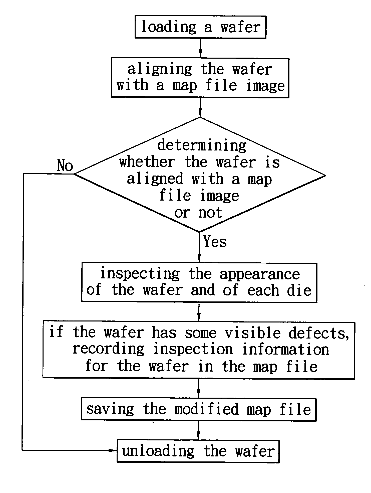
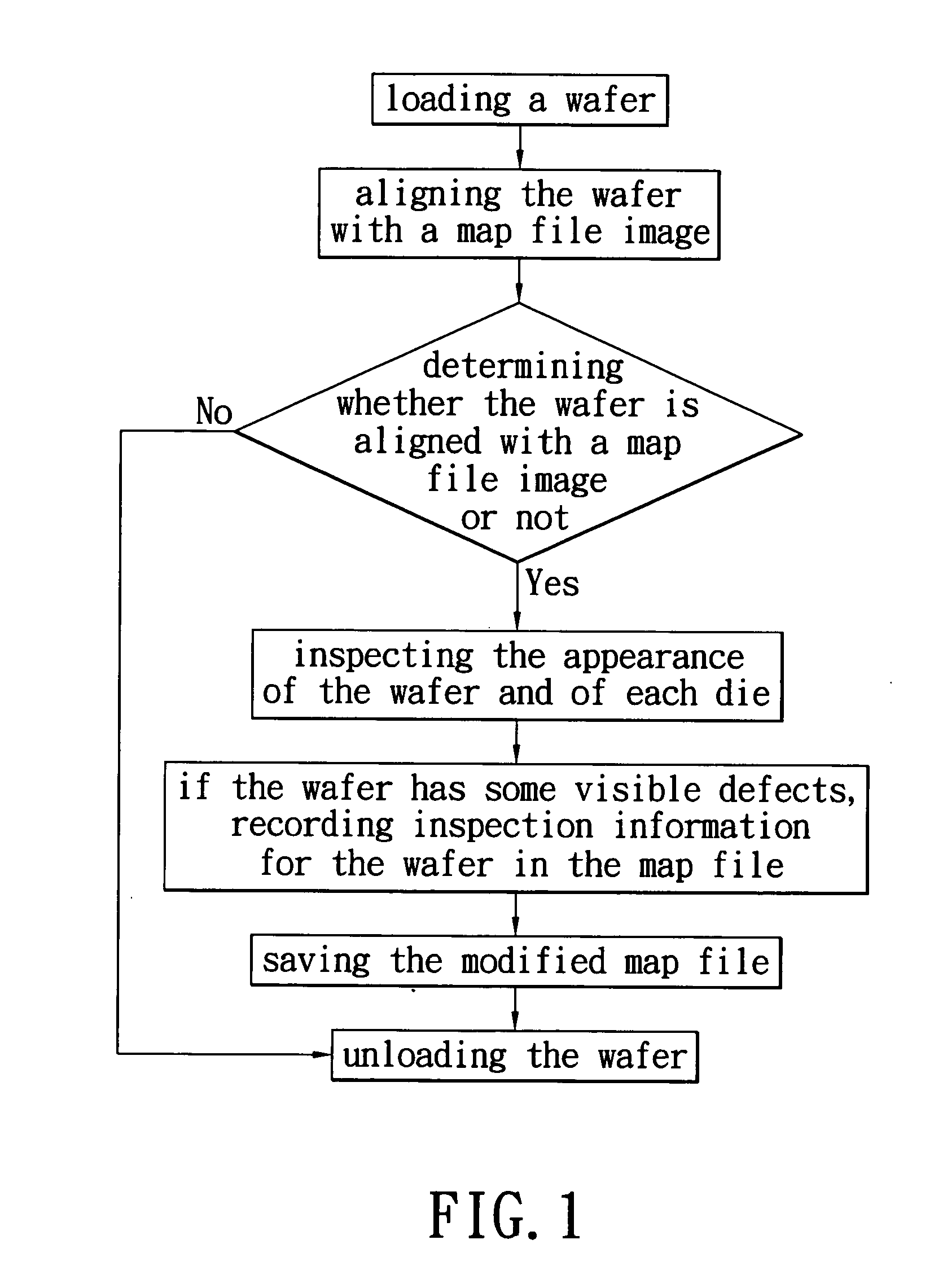
[0009]The primary object of the present invention is to provide a wafer testing method and inspection system that records the inspection result in an electronic map file so that the inspection time is reduced.
[0010]Another object of the present invention is to provide a wafer testing method. The system is provided for recording the inspecting result on the electric map file. The occasions of artificial mistakes will be reduced.
[0012]The operator performs visual inspection of each die and records the defects of the dies in the map file. Therefore, the examining rate is improved.

Problems solved by technology

Transferring the information recorded on paper to a computer system costs a lot of time and slows down the inspecting rate.
Furthermore, the inspection data is recorded by hand, and errors may occur occasionally, which reduces the inspection's precision.

Method used


Image

  • Wafer testing method
  • Wafer testing method
  • Wafer testing method

Examples


Embodiment Construction

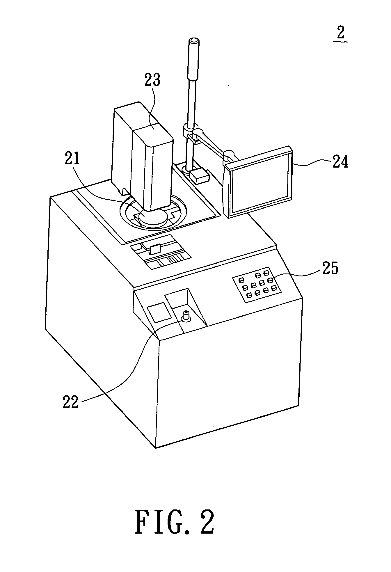
[0020]After the final step of manufacturing the integral circuit (IC) on the wafer, the wafer requires to be sorted into a plurality of single dies so that the packaging process can proceed on each die. However, before packaging the electric functions of each die have to be tested. Testing probes generally test each die and categorize the result of each tested die to output an electronic map file with a specific file type. In the preferred embodiment, the outputted map file is named as a map file with a first file type. The wafer testing system in the present invention also provides for visual inspection of the wafer and for directly modifying and recording the map file according to the inspection result.

[0021]Please refer to FIG. 2. The invention discloses a wafer testing system 2, and the wafer testing system 2 can be used to visually inspect the appearance of the wafer 1. Further, the wafer testing system 2 is compatible with the map file of the first file type that is outputted ...


PUM


Abstract

A wafer testing method for wafer testing system comprises the steps: loading a wafer and then positioning the wafer relatively to a map file image stored in a map file. The map file is of a first file type. The next step is inspecting the appearance of the wafer. When the user detects defects on the wafer, the positions of the defects are directly recorded in the map file and then the modified map file is saved. The map file can be directly modified when the wafer is in the testing procedure so that the testing time is reduced. Furthermore, the precision of the testing is improved.

Description

BACKGROUND OF THE INVENTION[0001]1. Field of the Invention[0002]The present invention relates to a wafer testing method and in particular to a wafer testing system provided for modifying the inspection result in a map file.[0003]2. Description of Prior Art[0004]The semiconductor industry is increasingly developed because personal mobile communication, electronic commercial business, global communication and digital home appliances are used in modern life. In the production of semiconductors, the main focus is on throughput rate and product yield.[0005]Some processes work directly on the semiconductor substrate, such as metal deposition, lithograph for patterning, and ion implantation so that an integrated circuit is formed on the substrate. To ensure that the circuitry is fully functional, electrical testers test the substrates after certain key processes. For example, after a metal deposition step is performed, it is determined whether the depth of the metal layer exceeds a thresho...

Claims


Application Information

Patent Timeline
IPC IPC(8): G01R31/26
CPCG01R31/2831H01L22/24G01R31/2894
Inventor WANG, BILYCHEN, HSIN-CHENGCHOU, MING-HAO
Owner YOUNGTEK ELECTRONICS
Learn More