Image coding apparatus and image coding method

a technology of image coding and coding method, which is applied in the field of image coding technology, can solve the problems of increasing the scale and cost of the circuitry, affecting the correct operation of the image coding apparatus as a whole, and undesirable countermeasures, so as to reduce the volume of data transfer

Active Publication Date: 2014-11-18
CANON KK
View PDF34 Cites 3 Cited by
  • Summary
  • Abstract
  • Description
  • Claims
  • Application Information

AI Technical Summary

Benefits of technology

[0027]The present invention is conceived in light of the problems of the conventional art described above, and reduces the data transfer volume required for motion detection as well as the amount of computation required for coding in an image coding apparatus and an image coding method that use both intraframe prediction coding and interframe prediction coding.
[0029]According to another aspect of the present invention, there is provided an image coding apparatus that codes a frame of a moving image in units of blocks, comprising: an intraframe prediction unit that generates, for an input moving image target block, a first prediction image block from within a same frame as the target block; an interframe prediction unit that generates, for the target block, a second prediction image block from within a frame different from that of the target block; a selection unit that selects one of either the intraframe prediction unit or the interframe prediction unit in accordance with a predetermined evaluation method; a local decoding unit that locally decodes a coded image; a first N-ary image conversion unit that reduces a number of gradations of the target block and generates a N-arized target block (where N is an integer equal to or greater than 2); a second N-ary image conversion unit that reduces the number of gradations of an output image of the local decoding unit and generates a N-arized image (where N is an integer equal to or greater than 2); and a storage unit that stores output of the second N-ary image conversion unit, the interframe prediction unit comprising: a motion detection unit that detects motion of the N-arized target block using output of the first N-ary image conversion unit and output from the storage unit; and a prediction image generation unit that generates the second prediction block based on detection results detected by the motion detection unit.
[0031]According to yet further aspect of the present invention, there is provided an image coding method for coding a frame of a moving image in units of blocks, comprising: intraframe prediction step of generating, for an input moving image target block, a first prediction image block from within a same frame as the target block; interframe prediction step of generating, for the target block, a second prediction image block from within a frame different from that of the target block; selection step of selecting one of either the intraframe prediction step or the interframe prediction step in accordance with a predetermined evaluation method; local decoding step of locally decoding a coded image; first N-ary image conversion step of reducing a number of gradations of the target block and generating a N-arized target block (where N is an integer equal to or greater than 2); second N-ary image conversion step of reducing the number of gradations of an output image in the local decoding step and generating a N-arized image (where N is an integer equal to or greater than 2); and storage step of storing output of the second N-ary image conversion step in a storage unit, the interframe prediction step comprising: motion detection step of detecting motion of the N-arized target block using output of the first N-ary image conversion step and output from the storage unit; and prediction image generation step of generating the second prediction block based on detection results detected in the motion detection step.
[0032]Such a configuration enables the data transfer volume required for motion detection as well as the amount of computation required for coding to be reduced in an image coding apparatus and an image coding method that use both intraframe prediction coding and interframe prediction coding.

Problems solved by technology

As a result, an increase in the transfer volume from the reference frame memory 604 to the search area RAM 602 affects processing by the other constituent elements that use the shared memory, and in some cases can interfere with the correct operation of the image coding apparatus as a whole.
However, such a countermeasure is undesirable because it increases the scale and cost of the circuitry.
In addition, new coding systems such as H.264, although they have better coding efficiency than previous coding systems, are complicated and require many calculations, making it difficult to restrain increases in coding time and increases in circuit scale.

Method used


Image

  • Image coding apparatus and image coding method
  • Image coding apparatus and image coding method
  • Image coding apparatus and image coding method

Examples


second embodiment

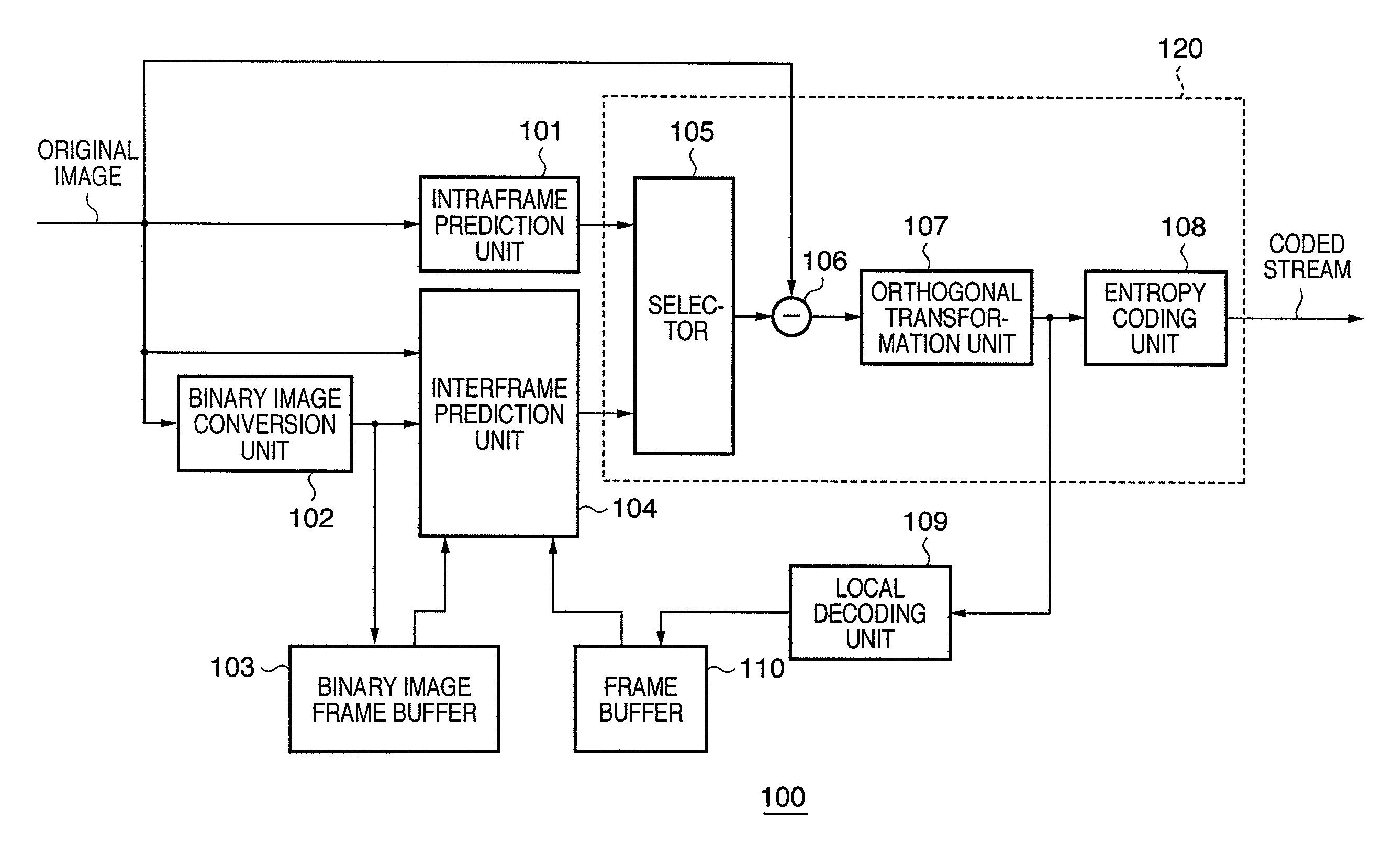
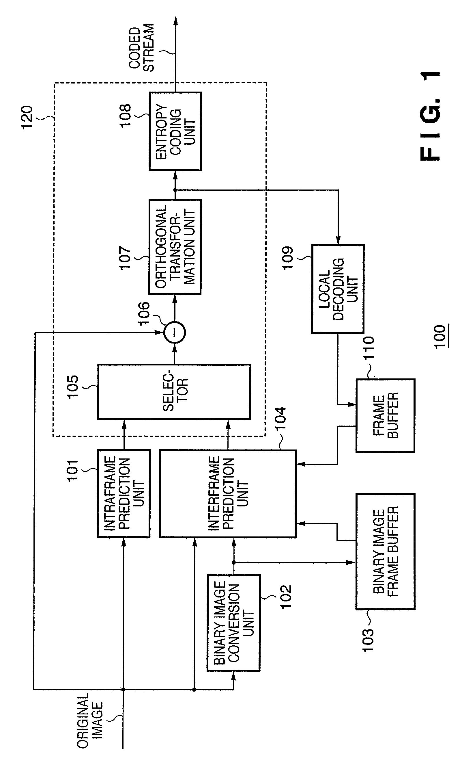
[0110]As a second embodiment of the present invention, the input of the binary image frame buffer 103 shown in FIG. 1 may be changed to a local decoding binary image and the same effect as in the first embodiment still obtained. A binary processing unit is provided and the output of the local decoding unit 109 is binarized and input to the binary image frame buffer 103. Although this embodiment requires a binary processing unit, it does make it possible to achieve coding having higher prediction-coding accuracy by using the locally decoded image.

Other Embodiments

[0111]In the embodiments described above, a description is given of a configuration that detects the first motion vector using a binary image. However, as can be easily understood by those of skill in the art, it is also possible to achieve the same effect by extracting the high-frequency components of the original image and using an image having an arbitrary number of gradations of reduced gradation number. Therefore, the b...


PUM


Abstract

To use both intraframe prediction coding and interframe prediction coding, and at the same time restrict a transfer volume of reference data used in motion detection in interframe prediction coding. In a coding apparatus that compression-codes moving images, both intraframe prediction coding and interframe prediction coding are applied and prediction coding is carried out using a prediction image produced by the coding system deemed to have the higher coding efficiency.

Description

BACKGROUND OF THE INVENTION[0001]1. Field of the Invention[0002]The present invention relates to image coding technology, and more particularly, to image coding technology that uses motion compensation.[0003]2. Description of the Related Art[0004]As compression coding systems set as international standards, ITU-T Recommendation H.264 or ISO / IEC international Standard 14496-10 (hereinafter simply H.264) and MPEG2 are known.[0005]In these coding systems, an image is divided into a plurality of rectangle blocks (macroblocks) and coded in units of macroblocks. In addition, use is made of the high temporal and spatial correlation between frame images that constitute moving images in order to reduce coding volume.[0006]As a coding system that makes use of temporal correlation, a compensation interframe prediction coding system is widely used. This system detects motion information (motion vectors) of coding target macroblocks and codes a difference between a prediction image generated usi...

Claims


Application Information

Patent Timeline
Patent Type & Authority Patents(United States)
IPC IPC(8): H04N7/00H04N19/57H04N19/50H04N19/103H04N19/53H03M7/36H04N19/51H04N19/107H04N19/11H04N19/134H04N19/136H04N19/139H04N19/189H04N19/19H04N19/196H04N19/423H04N19/503H04N19/593H04N19/60H04N19/61H04N19/625H04N19/80H04N19/91
CPCH04N19/59H04N19/43H04N19/53H04N19/11H04N19/513H04N19/533H04N19/57H04N19/593H04N19/50H04N19/51
Inventor IGARASHI, SUSUMU
Owner CANON KK
Why Eureka
Try Eureka