Network scanner

Active Publication Date: 2014-11-18
SHARP KK
View PDF27 Cites 0 Cited by
  • Summary
  • Abstract
  • Description
  • Claims
  • Application Information

AI Technical Summary

Benefits of technology

[0007]An object of the present invention is to provide a network scanner capable of suppressing the load on communicating to the min

Problems solved by technology

However, since a volume of the image data is generally large, the foregoing repetitive operations of checking the set reading conditions or confirming the image data would increase a load on communicating in the network, which affects other communications within the network.
Furthermore, an increased communication load would also make the communication time longer, which in turn causes such problem that it takes time for the user to obtain the image data

Method used


Image

  • Network scanner
  • Network scanner
  • Network scanner

Examples


Embodiment Construction

[0031]The following descriptions will explain one embodiment of the present invention in reference to FIG. 1 through FIG. 5, and FIGS. 6(a) and 6(b). It is needless to mention that the following preferred embodiments and examples are not intended to limit the scope of the present invention.

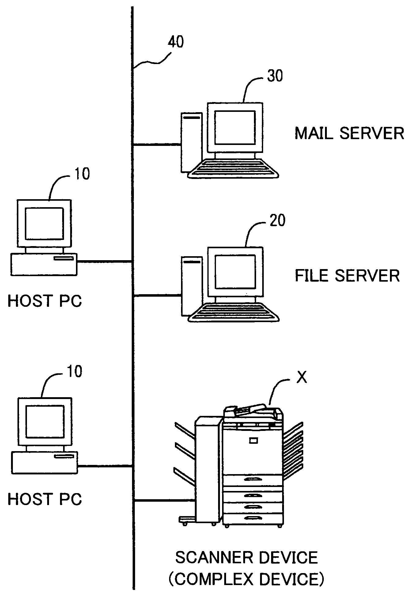
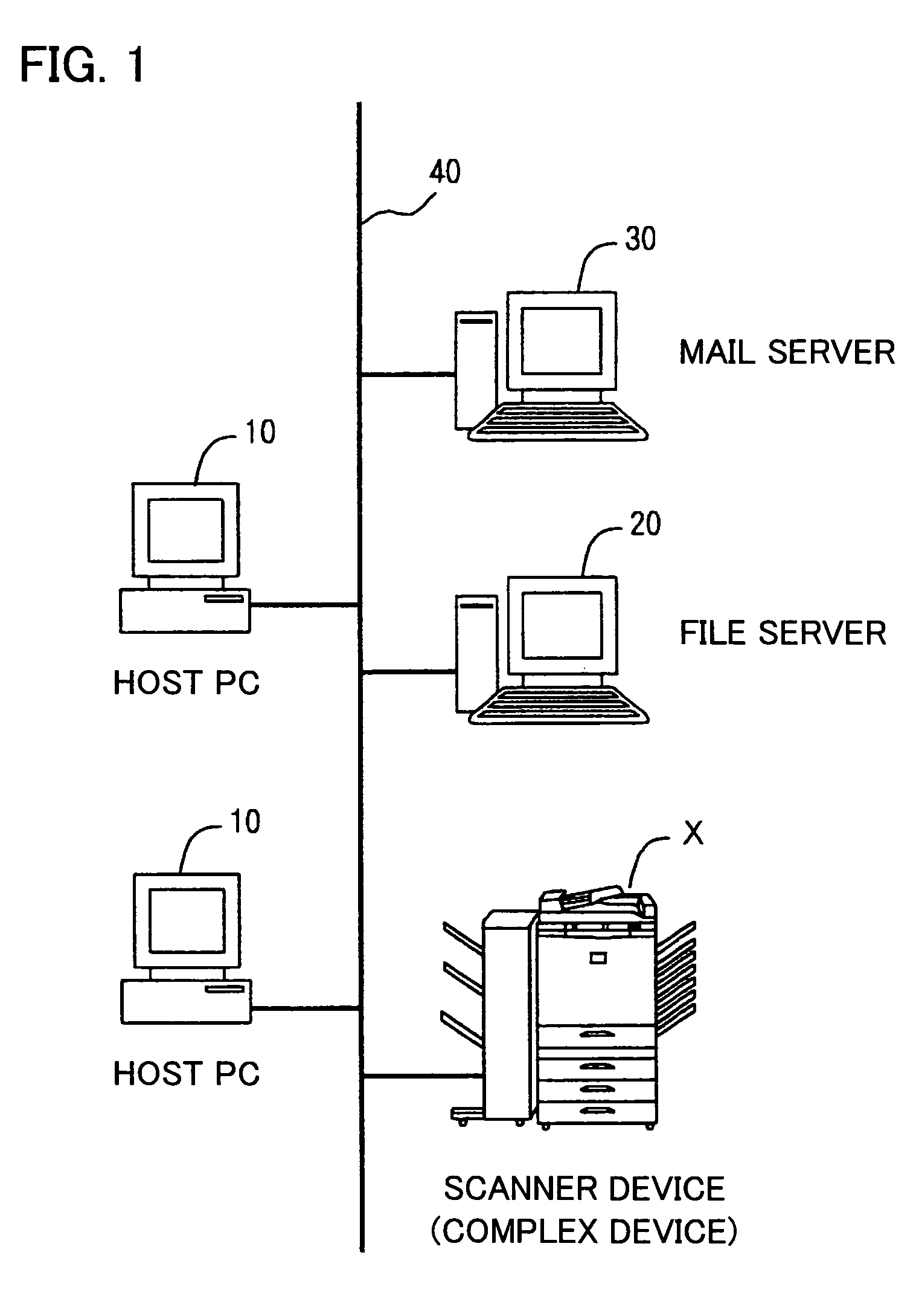
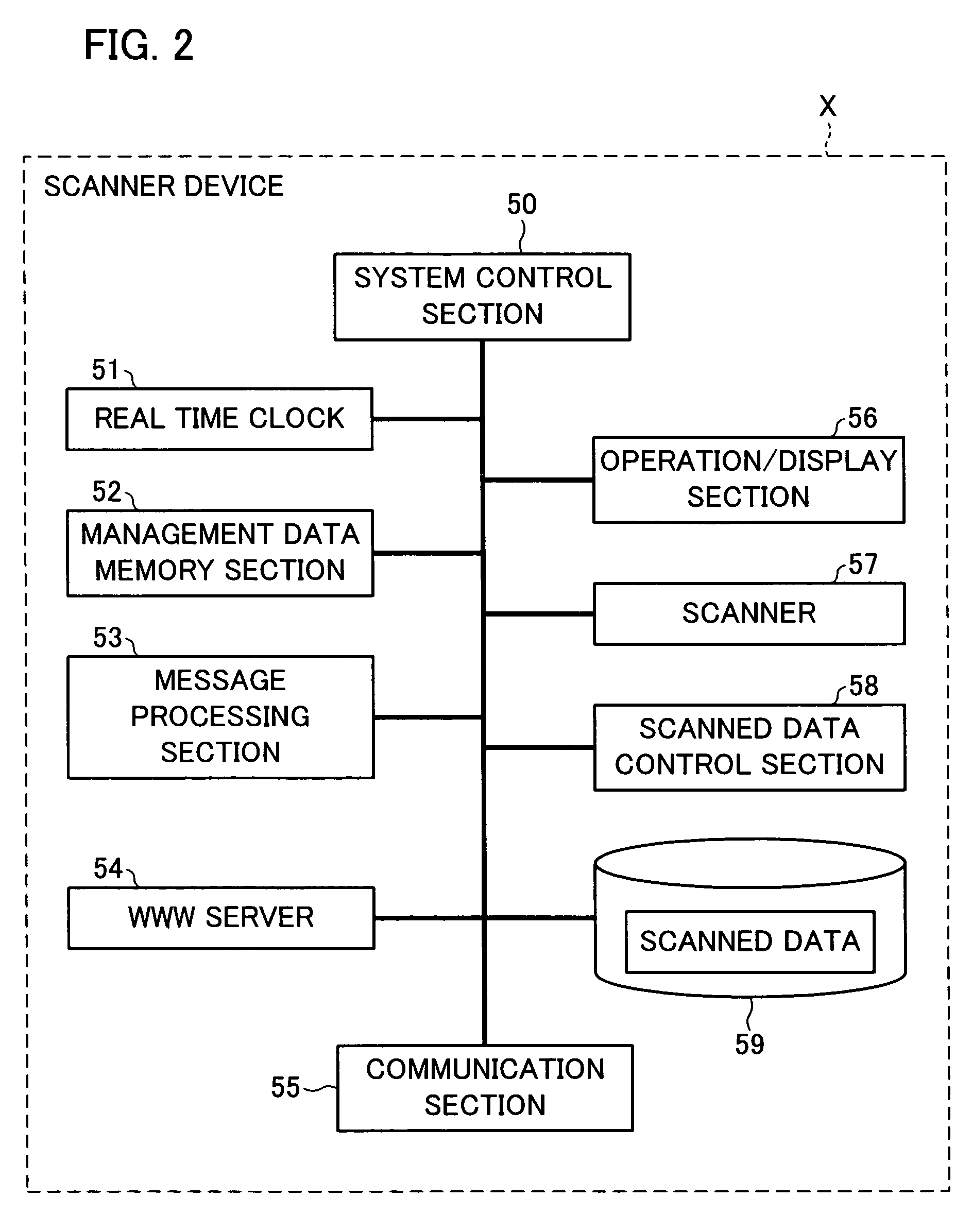
[0032]FIG. 1 is an explanatory view schematically showing the structure of an image reading system adopting a scanner device X in accordance with the embodiment of the present invention. FIG. 2 is a block diagram illustrating the schematic structure of the scanner device X in accordance with one embodiment of the present invention. FIG. 3 is a table showing the structure of management data for use in managing the scanned data by the scanner in accordance with the embodiment of the present invention.

[0033]FIG. 4 is a flowchart showing the image reading and image transmission processes in the scanner device X in accordance with the embodiment of the present invention. FIG. 5 is a flowchart showing t...


PUM


Abstract

A network scanner for transmitting image data as read from a document, which has been stored in a predetermined memory includes: a transmission part specifying means for specifying a part of the image data to be transmitted to said terminal(s); and specified data transmission means for transmitting the part of the image data as specified by the transmission part specifying means to the terminal(s). According to the foregoing structure, the load on communicating can be significantly reduced.

Description

FIELD OF THE INVENTION[0001]The present invention relates to a network scanner for transmitting image data obtained by reading from a document to at least one of terminals connected in a network.BACKGROUND OF THE INVENTION[0002]In recent years, network scanners are used generally, wherein image data obtained by reading from a document are stored in a predetermined memory section, and the image data as read are transmitted to one or a plurality of terminals. Japanese Unexamined Patent Application No. 2000-349952 (published on Dec. 15, 2000) discloses a network scanner wherein a hyper text (so-called thumbnail) that includes a list of reduced images of image data as read by a network scanner is transmitted to the terminal, and by making an access to the linked address where reduced images are stored, the corresponding image data are transmitted to the terminal of the requesting end.[0003]When reading the document by the foregoing network scanner, the user generally sets various image ...

Claims


Application Information

Patent Timeline
IPC IPC(8): H04L29/08G06F15/16H04N1/00H04N1/32
CPCH04N2201/3204H04N2201/3216H04N1/32368H04N2201/3295H04N2201/3274H04N2201/0081H04N2201/3222H04N1/00241H04L69/329H04N2201/3214H04N1/00236H04N1/32122
Inventor SAKIYAMA, MASAHIRONAGAI, YUSUKE
Owner SHARP KK
Why Eureka
Try Eureka