Load control device having a low-power mode

a load control and low-power technology, applied in non-electric variable control, process and machine control, instruments, etc., can solve the problems of small dimming range, worst-case conditions that are not encountered in practice, etc., and achieve the effect of less curren

Active Publication Date: 2014-11-18
LUTRON TECH CO LLC
View PDF36 Cites 26 Cited by
  • Summary
  • Abstract
  • Description
  • Claims
  • Application Information

AI Technical Summary

Benefits of technology

[0025]According to another embodiment of the present invention, a load control device for control of the power delivered from an AC power source to an electrical load comprises: (1) a controllably conductive device adapted to be coupled between the AC power source and the electrical load for controlling the power delivered to the load; (2) a microprocessor coupled to the controllably conductive device for controlling the controllably conductive device; (3) a communication circuit coupled to the microprocessor for transmitting and / or receiving digital messages; and (4) a power supply adapted to draw current from the AC power source through the electrical load for generating a DC voltage across an energy storage capacitor for powering the microprocessor and the communication circuit. The microprocessor is able to operate the load control device in a low-power mode during which the microprocessor causes the communication circuit to draw less current from the energy storage capacitor.

Problems solved by technology

However, these worst-case conditions are often not encountered in practice.
Some prior art dimmers have held the minimum off-time constant under all conditions, and thus have suffered from a smaller dimming range than would otherwise be possible.

Method used


Image

  • Load control device having a low-power mode
  • Load control device having a low-power mode
  • Load control device having a low-power mode

Examples


Embodiment Construction

[0039]The foregoing summary, as well as the following detailed description of the preferred embodiments, is better understood when read in conjunction with the appended drawings. For the purposes of illustrating the invention, there is shown in the drawings an embodiment that is presently preferred, in which like numerals represent similar parts throughout the several views of the drawings, it being understood, however, that the invention is not limited to the specific methods and instrumentalities disclosed.

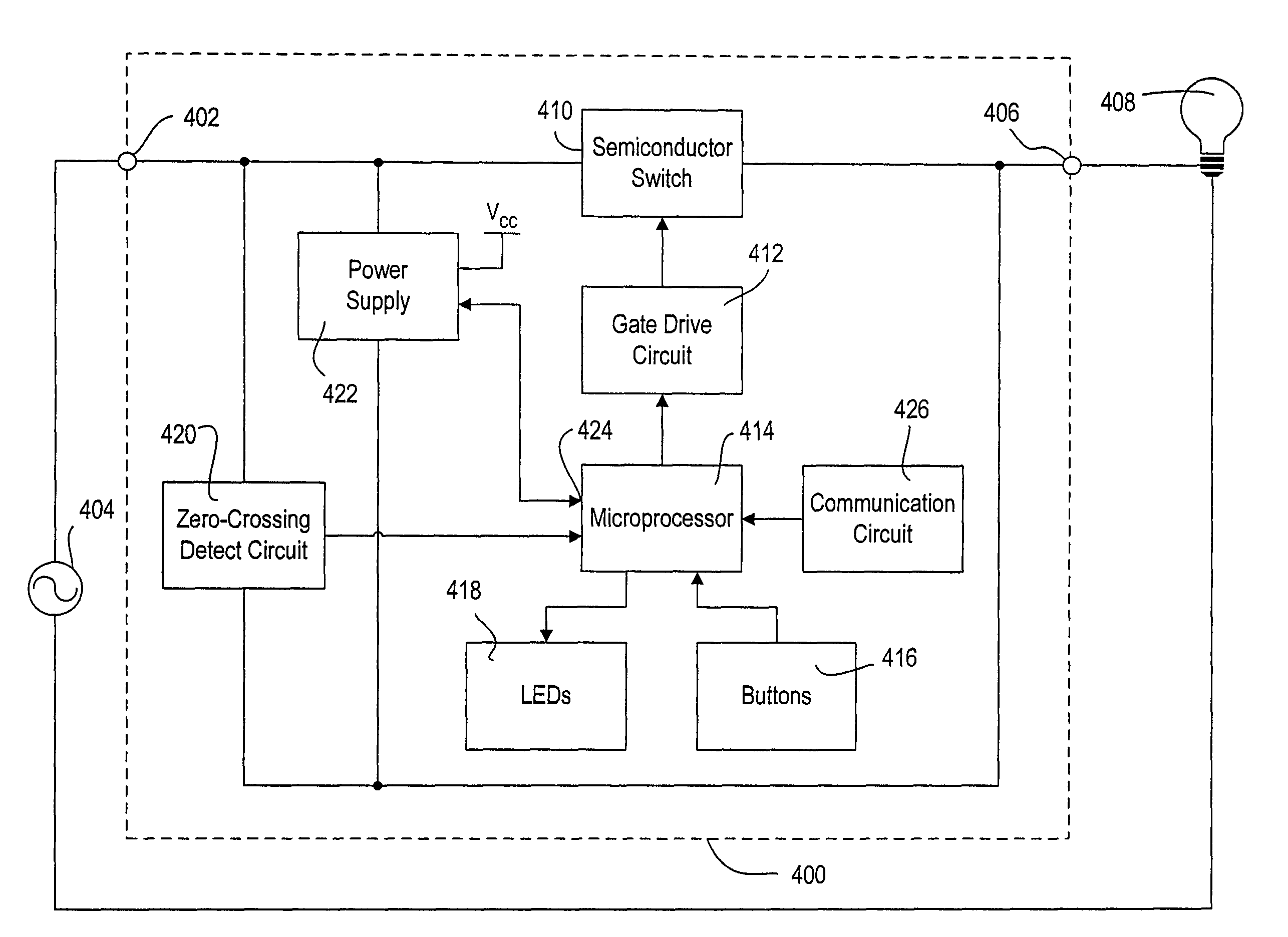
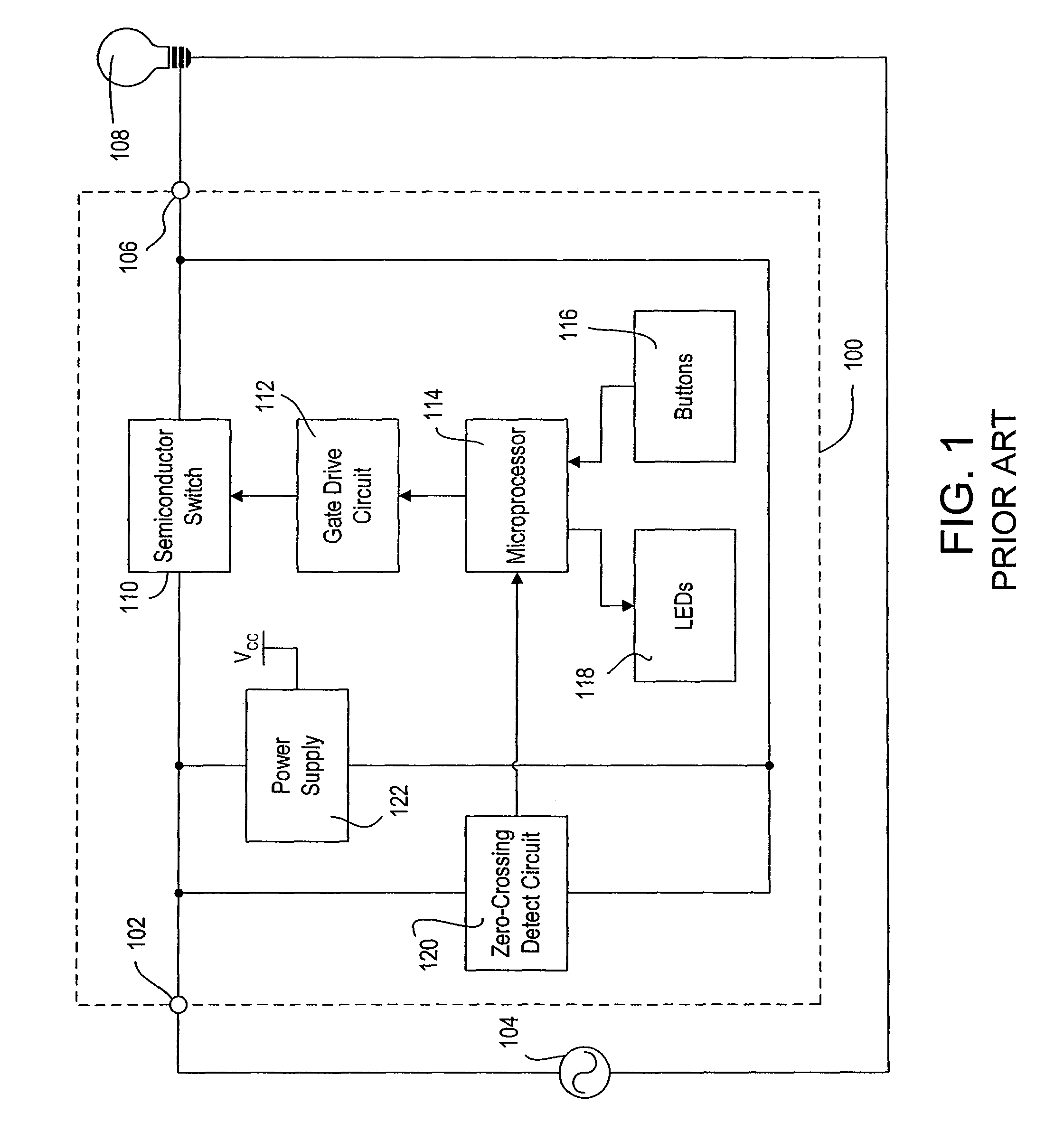
[0040]FIG. 4 is a simplified block diagram of a two-wire dimmer 400 according to the present invention. The dimmer 400 includes many similar blocks as the dimmer 100 of FIG. 1, which have the same function as described previously. However, those components of the dimmer 400 that differ from the prior art dimmer 100 will be described in greater detail below.

[0041]The dimmer 400 includes a controllably conductive device, e.g., a bidirectional semiconductor switch 410, that is adap...


PUM


Abstract

A load control device for control of the power delivered from an AC power source to an electrical load comprises a power supply and a microprocessor that is able to operate the load control device in a low-power mode. The load control device may further comprise at least one visual indicator controlled by the microprocessor to provide visual feedback, where the microprocessor illuminates the visual indicator when the load is on and to turns the visual indicator off when the load is off during the low-power mode. The load control device may comprise a communication circuit coupled to the microprocessor for transmitting and / or receiving digital messages the microprocessor cause the communication circuit to draw less current from the power supply during the low-power mode. The microprocessor may operate in the low-power mode if the magnitude of a voltage of the power supply drops below a predetermined threshold.

Description

CROSS REFERENCE TO RELATED APPLICATIONS[0001]This application is a continuation-in-part application of commonly-assigned, co-pending U.S. patent application Ser. No. 12 / 369,395, filed Feb. 11, 2009, which is a continuation application of U.S. patent application Ser. No. 11 / 480,146, filed Jun. 30, 2006, now U.S. Pat. No. 7,546,473, issued Jun. 9, 2009, which claims priority from U.S. Provisional Patent Application No. 60 / 695,784, filed Jun. 30, 2005, all entitled DIMMER HAVING A MICROPROCESSOR-CONTROLLED POWER SUPPLY, the entire disclosures of which are hereby incorporated by reference.BACKGROUND OF THE INVENTION[0002]1. Field of the Invention[0003]The present invention relates to a two-wire load control device, specifically a two-wire dimmer switch having a microprocessor and a power supply for generating a direct-current (DC) voltage for powering the microprocessor, where the microprocessor is able to operate the dimmer switch in a low-power mode.[0004]2. Description of the Related...

Claims


Application Information

Patent Timeline
Patent Type & Authority Patents(United States)
IPC IPC(8): G06F1/32G06F1/26
CPCY02B20/148H05B39/048Y02B20/146H05B39/044Y02B20/00
Inventor NEWMAN, JR., ROBERT C.SALVESTRINI, CHRISTOPHER J.
Owner LUTRON TECH CO LLC
Why Eureka
Try Eureka