Rotary knife with mechanism for controlling blade housing

a technology of rotating blades and rotary knives, which is applied in the direction of rind cutting-off apparatus, poultry processing, fish skinning, etc., can solve the problems of requiring the cutting edge of annular blades is quickly dull and requires frequent sharpening or replacement, and the maintenance of conventional rotary knives is not easy

Active Publication Date: 2014-11-25
HANTOVER
View PDF20 Cites 10 Cited by
  • Summary
  • Abstract
  • Description
  • Claims
  • Application Information

AI Technical Summary

Problems solved by technology

However, it has been found that prior art rotary knives suffer from certain limitations.
For instance, the high-speed rotational movement of the annular blade, which is ideal for quickly and efficiently processing meat, causes the cutting edge of the annular blade to quickly become dull and require frequent sharpening or replacement.
Conventional rotary knives also suffer from problems associated with blade maintenance.
For example, conventional knives require an inordinate amount of time to remove and install the blade during blade maintenance.
Furthermore, the process of installing the blade requires precise blade alignment relative to the blade housing, and the blade housing construction makes such alignment difficult to achieve.

Method used


Image

  • Rotary knife with mechanism for controlling blade housing
  • Rotary knife with mechanism for controlling blade housing
  • Rotary knife with mechanism for controlling blade housing

Examples


Embodiment Construction

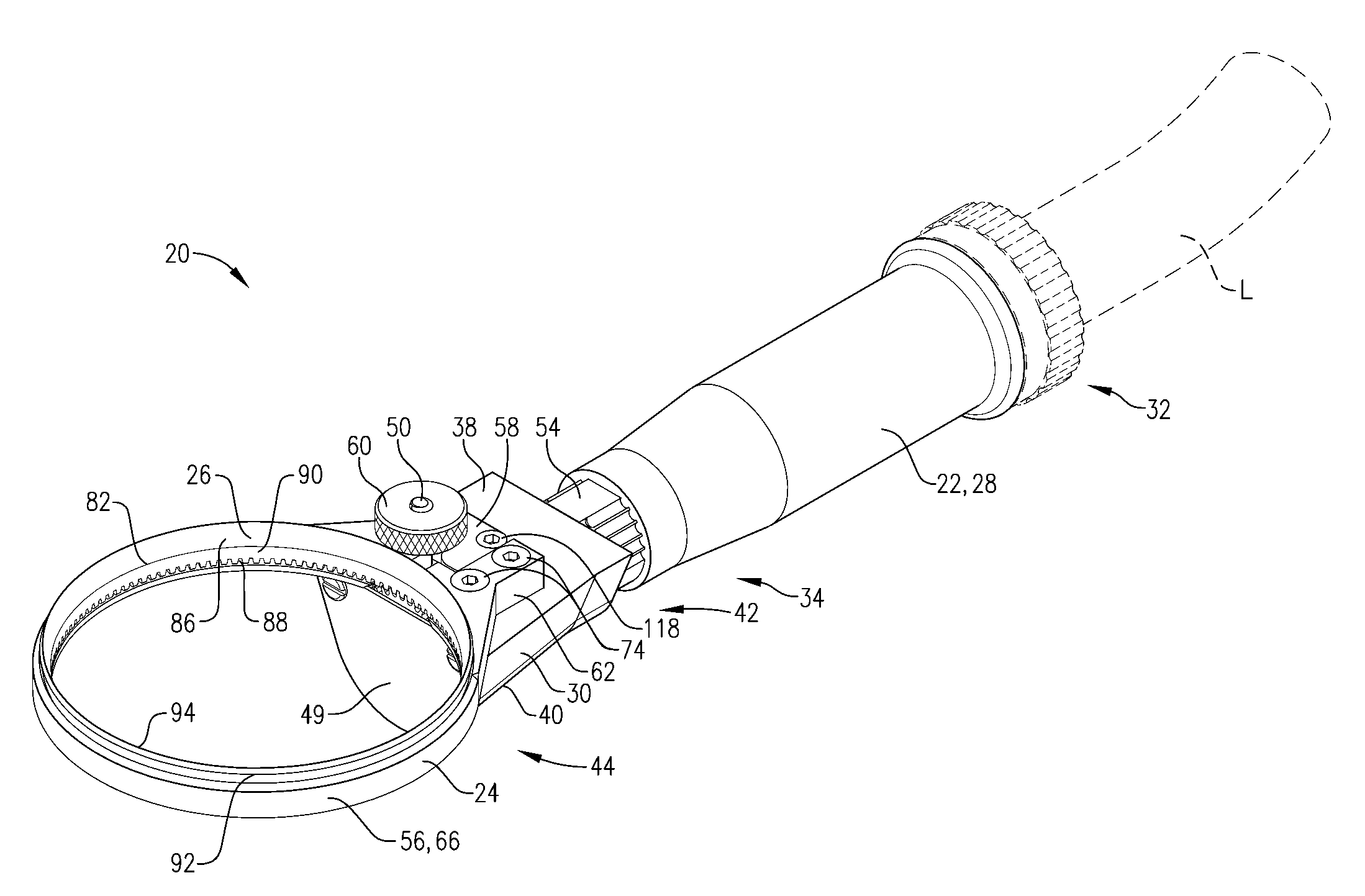
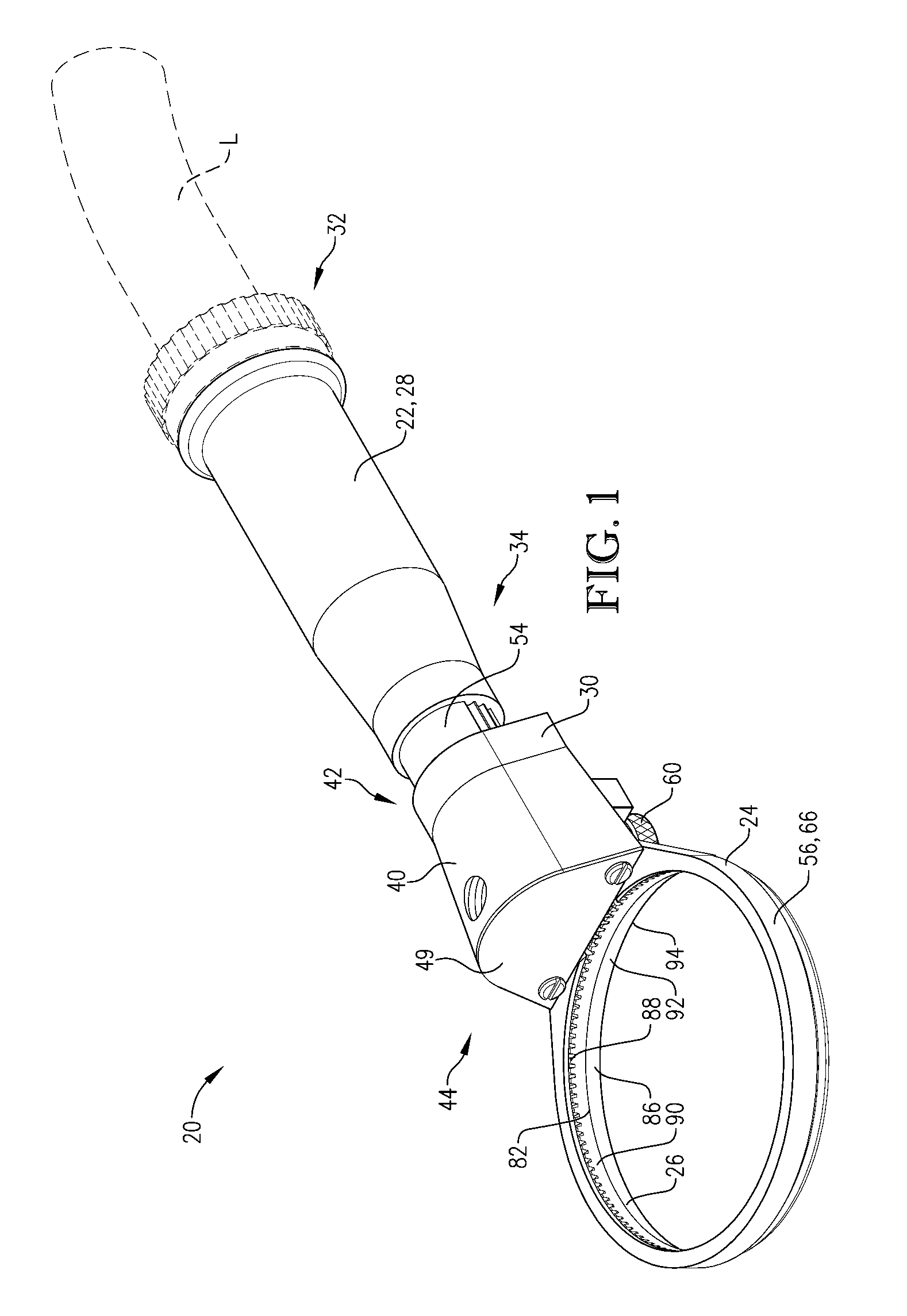
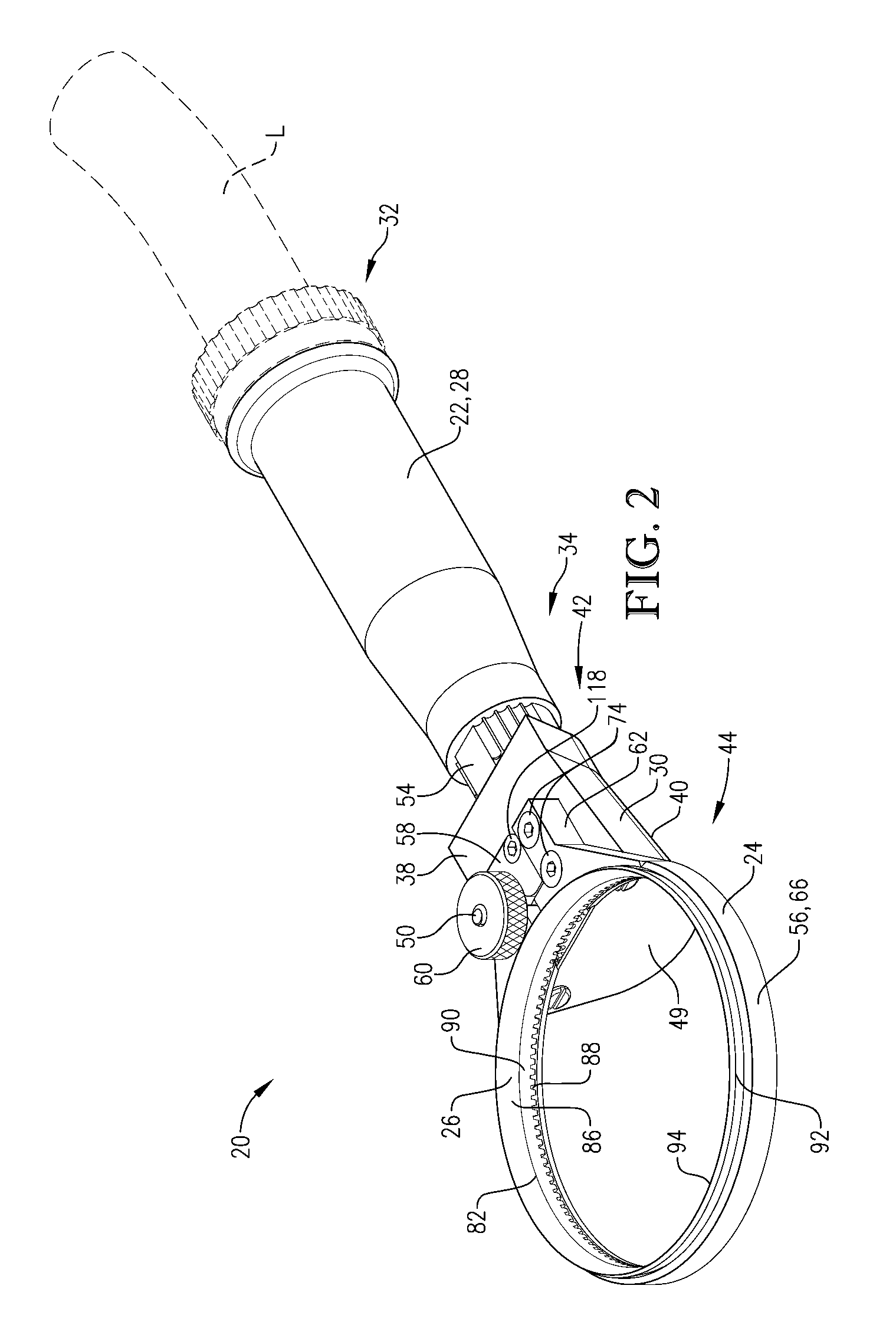
[0023]Turning initially to FIGS. 1 and 2, a rotary knife 20 is constructed in accordance with a preferred embodiment of the present invention. The illustrated rotary knife 20 is particularly well suited for use in meat processing facilities, although other knife applications are entirely within the ambit of the present invention. The illustrated rotary knife 20 is preferably pneumatically powered by a pressurized air source (not shown), e.g., an air compressor. However, the principles of the present invention are equally applicable where the rotary knife is driven by alternative external power sources, such as sources that transmit power through hydraulic power or electrical power. The rotary knife 20 broadly includes a handle 22, a blade carrier assembly 24, and a rotating blade assembly 26.

[0024]Turning to FIGS. 1 and 2, the handle 22 includes a grip housing 28 and a base 30. The grip housing 28 has a generally cylindrical shape and extends between a proximal connector end 32 for ...


PUM


Abstract

A rotary knife includes a handle, a rotatable annular blade, and a blade carrier assembly. The blade carrier assembly includes an expandable blade housing operably coupled to the handle and configured to removably support the blade. The blade housing is movable relative to the handle between a blade-securing condition, in which the blade housing securely supports the blade for rotational operation, and a relatively expanded blade-releasing condition, in which the blade housing permits removal and installation of the blade relative to the blade housing. The carrier assembly includes a lever mechanism shiftably mounted relative to the handle and configured when shifted to expand the blade housing from the blade-securing condition to the blade-releasing condition.

Description

BACKGROUND[0001]1. Field[0002]The present invention relates generally to powered knives, such as those commonly used in meat processing plants. More specifically, embodiments of the present invention concern a rotary knife with a rotating blade assembly.[0003]2. Discussion of Prior Art[0004]Powered rotary knives that are used in the meat processing industry for dressing an animal carcass are known in the art. The process of dressing the carcass normally involves the removal of meat and fat from various bones as well as cutting various bones. Powered rotary knives enable workers to perform this process with great efficiency. Such prior art knives include a housing and a rotary knife assembly with an endless annular blade that can be removed for sharpening or replacement.[0005]However, it has been found that prior art rotary knives suffer from certain limitations. For instance, the high-speed rotational movement of the annular blade, which is ideal for quickly and efficiently processi...

Claims


Application Information

Patent Timeline
Patent Type & Authority Patents(United States)
IPC IPC(8): B26D1/14A22C17/04B26D1/28A22C17/12B26D7/22B26D7/26
CPCB26D1/28B26D7/225B26D7/2621B26D1/14A22C17/12B26D7/2614B26B25/002
Inventor LEVSEN, CLARK, A.
Owner HANTOVER
Why Eureka
Try Eureka