
Fan heater with humidifier

a fan heater and humidifier technology, applied in the direction of combustion air/fuel air treatment, machine/engine, combustion gas purification/modification, etc., can solve the problems of air so dry that another kind of discomfort is felt, dry air may irritate or even injure such sensitive organs, and the additional cost of the humidifier is inevitable. , to achieve the effect of preventing the air around the fan heater from being excessively dry

Active Publication Date: 2014-11-25
PUC PERFECT UNION
View PDF11 Cites 2 Cited by
  • Summary
  • Abstract
  • Description
  • Claims
  • Application Information

AI Technical Summary

Benefits of technology

The present invention is a fan heater with a humidifier that provides warm air and moisture simultaneously. The fan heater has an integrated structure that prevents the air around it from being too dry. The warm air generation mechanism uses a thermistor heating element and a quartz electric heating tube to efficiently provide concentrated heat. The compact structure effectively supplies warm air and moisture, making the air in the space where the fan heater is used not too dry.

Problems solved by technology

While these products are intended to provide warmth to spaces of specific sizes, continued use of electric heaters or fan heaters indoors will make the air so dry that another kind of discomfort is felt.
The overly dry air may irritate or even injure such sensitive organs as the skin and the mucous membrane.
However, whether the fan heater and the humidifier are purchased separately or at the same time, the additional cost of the humidifier is inevitable.
The humidifier also occupies extra space.
Nevertheless, this structure has low heating efficiency due to the fact that the components near the quartz electric heating tube are subject to prolonged overheating and that the heat source cannot be released.
This structure, however, incurs high manufacturing costs and adds to the complexity of the control procedure of the humidifier.
Besides, the water level in the humidifier cannot be known from the outside and can only be detected by the control unit.
As such, the conventional humidifier leaves much room for improvement.

Method used


Image

  • Fan heater with humidifier
  • Fan heater with humidifier
  • Fan heater with humidifier

Examples


Embodiment Construction

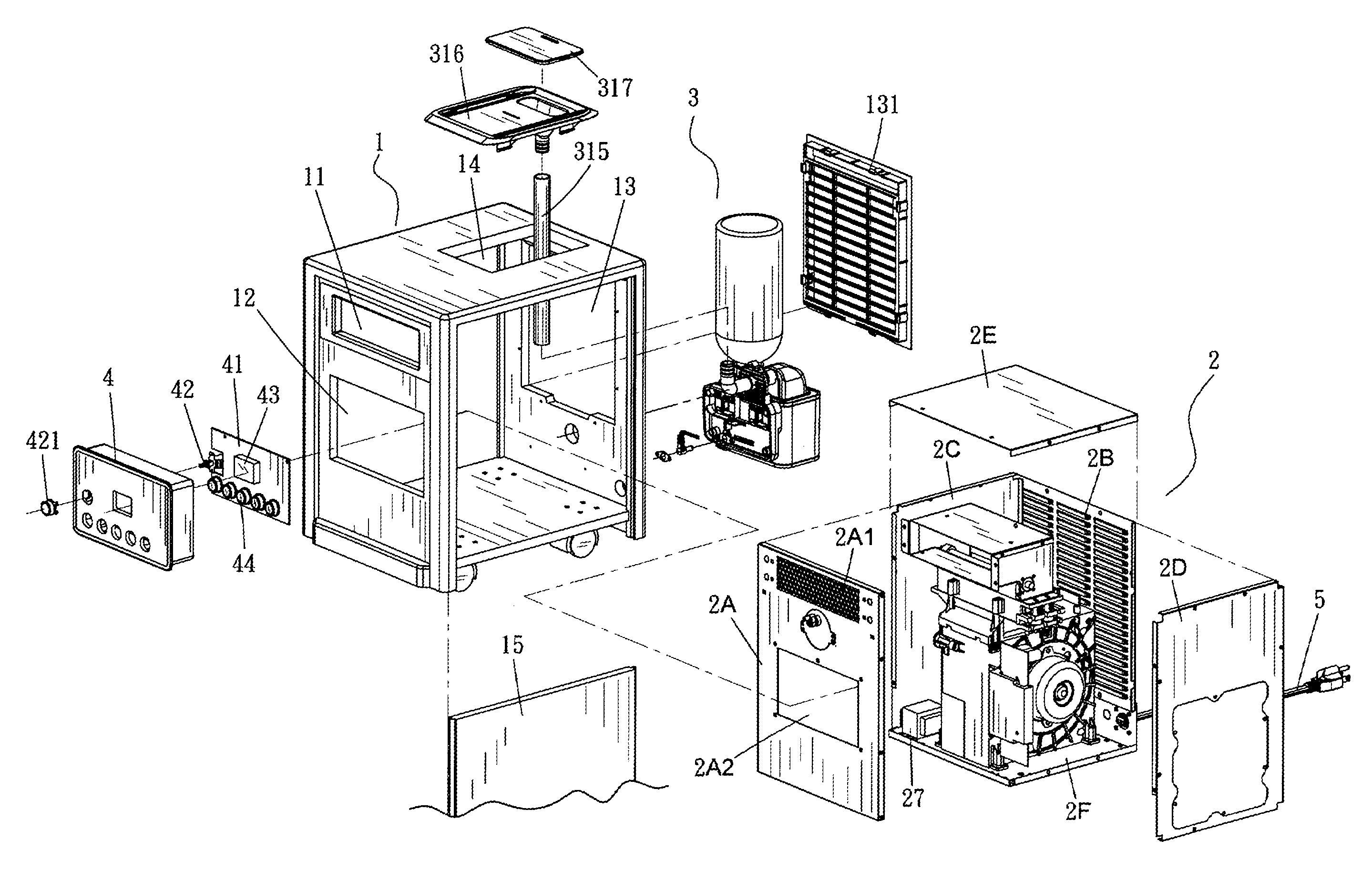
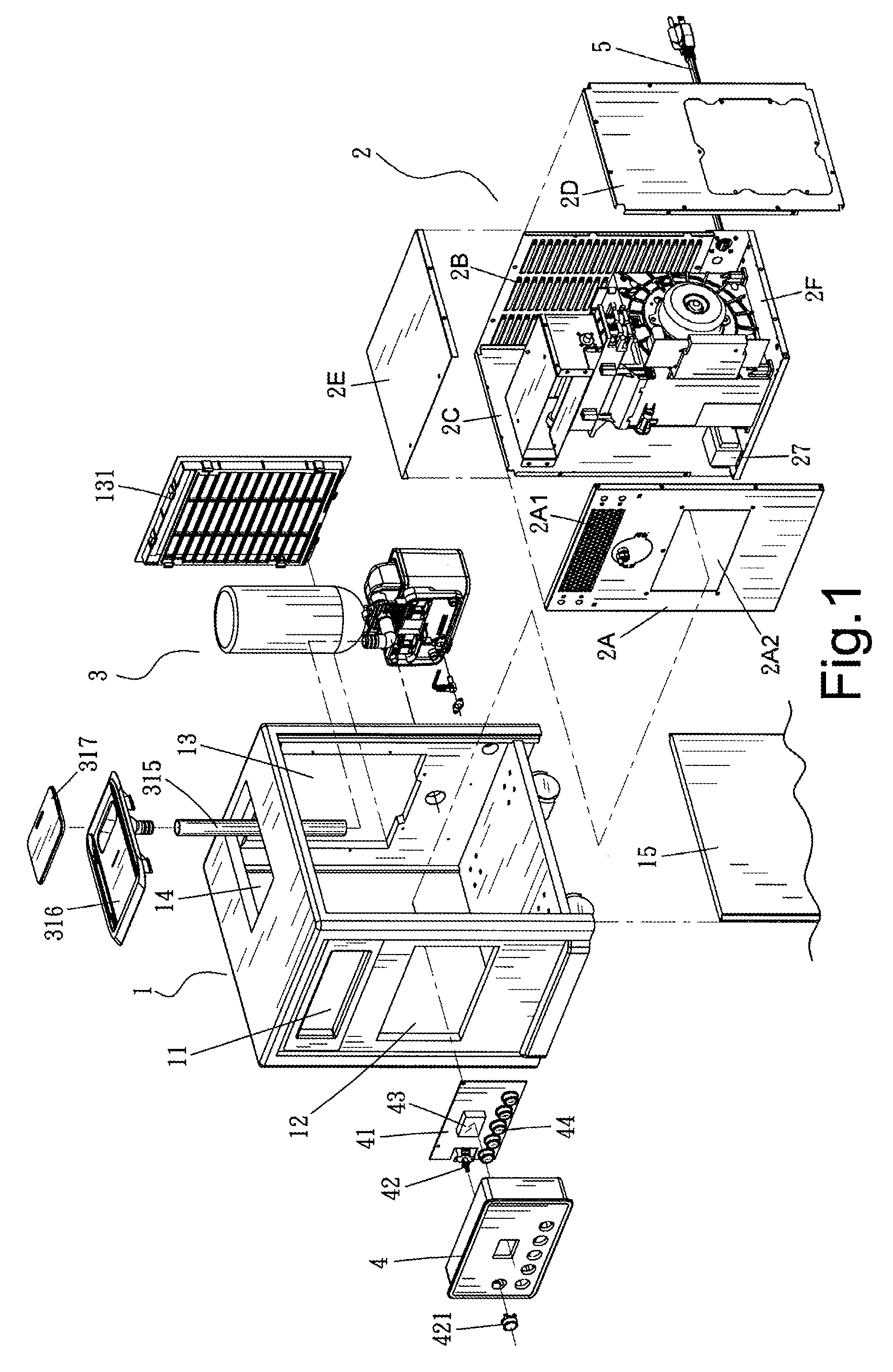
[0021]Referring to FIG. 1, a fan heater with a humidifier as disclosed by the present invention essentially includes a housing 1, a warm air generation mechanism 2 provided in the housing 1, a humidification mechanism 3 provided in the housing 1, a control panel 4 provided on the front side of the housing 1, and an AC power cord 5.

[0022]As for the housing 1, a warm air outlet 11 and a control panel penetration hole 12 are provided at the front end, an air inlet 13 connected with a filter plate 131 is provided at the rear end, a mist outlet 14 is provided at the top end, and an openable inspection plate 15 is provided on one side.

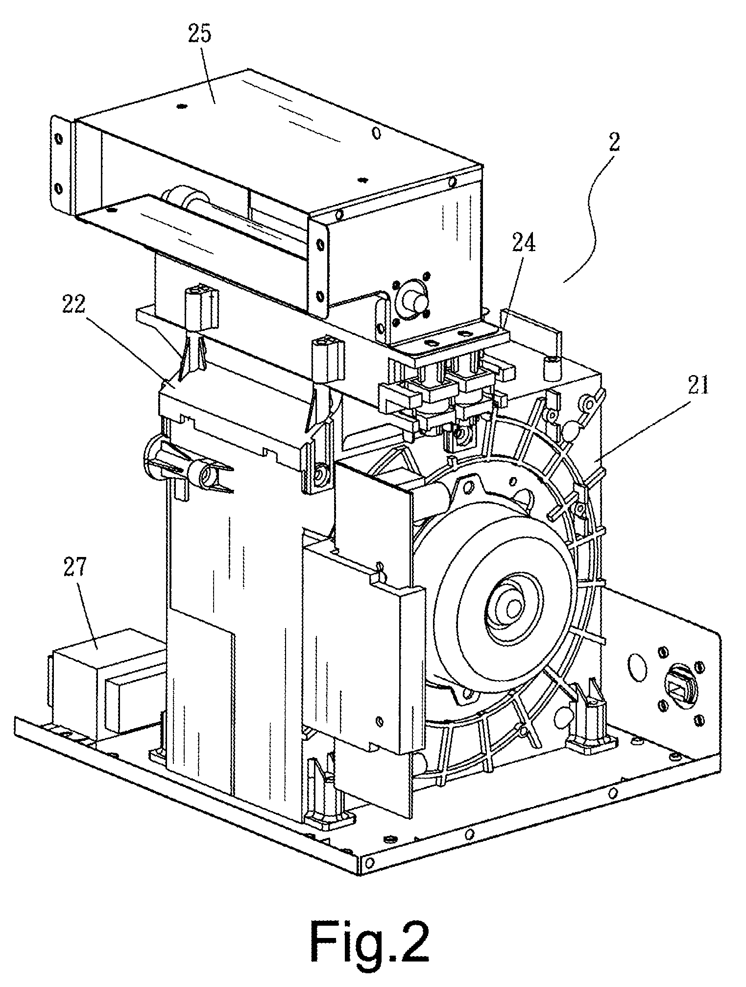
[0023]The warm air generation mechanism 2 includes a fan heater case which is composed of a metallic front plate 2A, a rear ventilation plate 2B, a left-side plate 2C, a right-side plate 2D, a cover plate 2E, and a bottom plate 2F. The front plate 2A is provided with a wind mesh 2A1 and a control panel installation hole 2A2.

[0024]Referring to FIG. 1 through ...


PUM

PropertyMeasurementUnit
temperaturesaaaaaaaaaa
sizesaaaaaaaaaa
timeaaaaaaaaaa

Abstract

A fan heater with a humidifier includes a housing in which both a warm air generation mechanism for generating warm air and a humidification mechanism for generating a mist are provided. The fan heater with the humidifier is characterized by its integrated structure for effectively providing warm air and appropriate moisture at the same time, so as to prevent the air around the fan heater from being too dry.

Description

BACKGROUND OF THE INVENTION[0001]1. Technical Field[0002]The present invention relates to a fan heater with a humidifier, wherein a warm air generation mechanism for generating warm air and a humidification mechanism for generating a mist are provided in the same housing to effectively supply warm air and appropriate moisture at the same time.[0003]2. Description of Related Art[0004]As the temperatures in many parts of the world can be intolerably low, the uncomfortable sensation of coldness has given rise to the development of electric heaters, fan heaters, and the like. While these products are intended to provide warmth to spaces of specific sizes, continued use of electric heaters or fan heaters indoors will make the air so dry that another kind of discomfort is felt. The overly dry air may irritate or even injure such sensitive organs as the skin and the mucous membrane.[0005]Conventionally, fan heaters and humidifiers are separate devices independent of each other. A consumer ...

Claims


Application Information

Patent Timeline
Patent Type & Authority Patents(United States)
IPC IPC(8): B01F3/04
CPCF24F6/02F24F2006/008F24F6/12F24H3/0405F24H3/0411F24H3/12F24H9/0063F24H9/1863
Inventor CHING, CHAN
Owner PUC PERFECT UNION
Learn More