Device and method for stiffening and holding a workpiece for machining

a technology of workpiece and clamping table, which is applied in the direction of metal-working holders, positioning apparatuses, supports, etc., can solve the problems of insufficient machined areas, relatively high clamping table price, and insufficient machined workpiece contours, so as to maintain the contour of workpiece and reduce the cost

Inactive Publication Date: 2014-11-25
FOOKE GMBH
View PDF29 Cites 2 Cited by
  • Summary
  • Abstract
  • Description
  • Claims
  • Application Information

AI Technical Summary

Benefits of technology

[0006]The aim of the invention is to create a fixture or device for stiffening a large, thin workpiece that has low inherent stiffness, i.e., to provide a fixture that provides excellent support of the workpiece and that can be produced economically.
[0007]The invention is a flexible clamping plate that uses suction to hold the workpiece against the plate. The plate is a composite construction with at least three layers: a back layer, an intermediate layer, and a contact layer. The contact layer is the side of the clamping plate that is brought into contact with the workpiece to be machined. Air channels that penetrate through the contact layer and into the intermediate layer create layers that are deformable, thereby imparting a flexibility to the plate, such that the plate is easily adaptable to the relatively large radii of large workpieces.
[0008]The aforementioned air channels may be constructed as intersecting grooves, which results in a two-directional flexibility of the clamping plate. This makes it possible to place the clamping plate on workpieces that are spherically curved.

Problems solved by technology

Any flexibility in the workpiece can cause it to yield under the machining pressure of the tool, with the result that the workpiece is not machined according to specification.
Each individual actuator can cost more then 1,000.00 Euros and, because the actuators should be placed as close together as possible to ensure optimum support of the workpiece, such clamping tables are relatively expensive.
These areas are then insufficiently machined.
Machining to specification the requires that the workpiece be re-worked, and this re-work machining requires a great deal of effort regarding fixtures and devices and measurement techniques.

Method used


Image

  • Device and method for stiffening and holding a workpiece for machining
  • Device and method for stiffening and holding a workpiece for machining
  • Device and method for stiffening and holding a workpiece for machining

Examples


Embodiment Construction

[0033]The present invention will now be described more fully in detail with reference to the accompanying drawings, in which the preferred embodiments of the invention are shown. This invention should not, however, be construed as limited to the embodiments set forth herein; rather, they are provided so that this disclosure will be complete and will fully convey the scope of the invention to those skilled in the art.

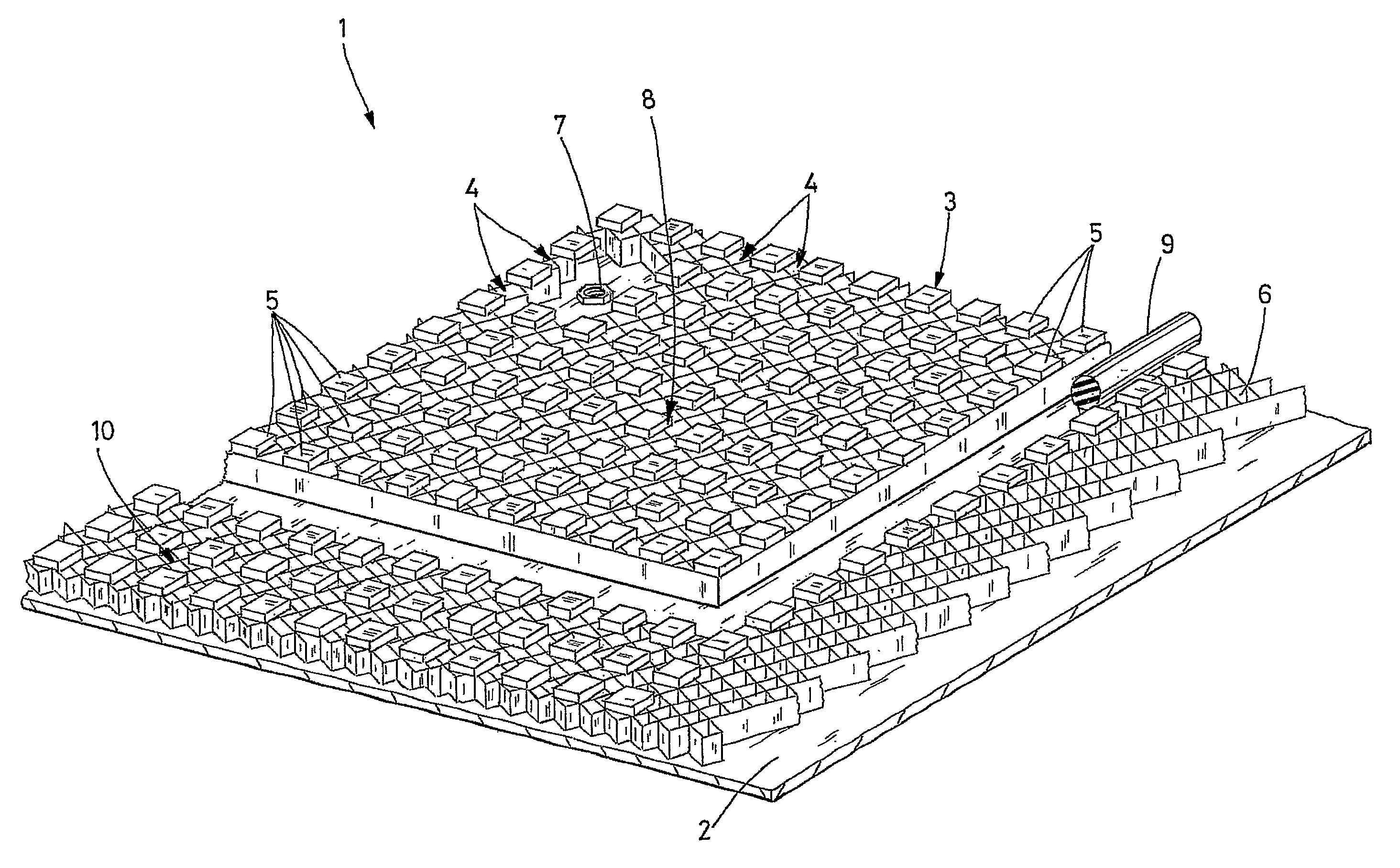
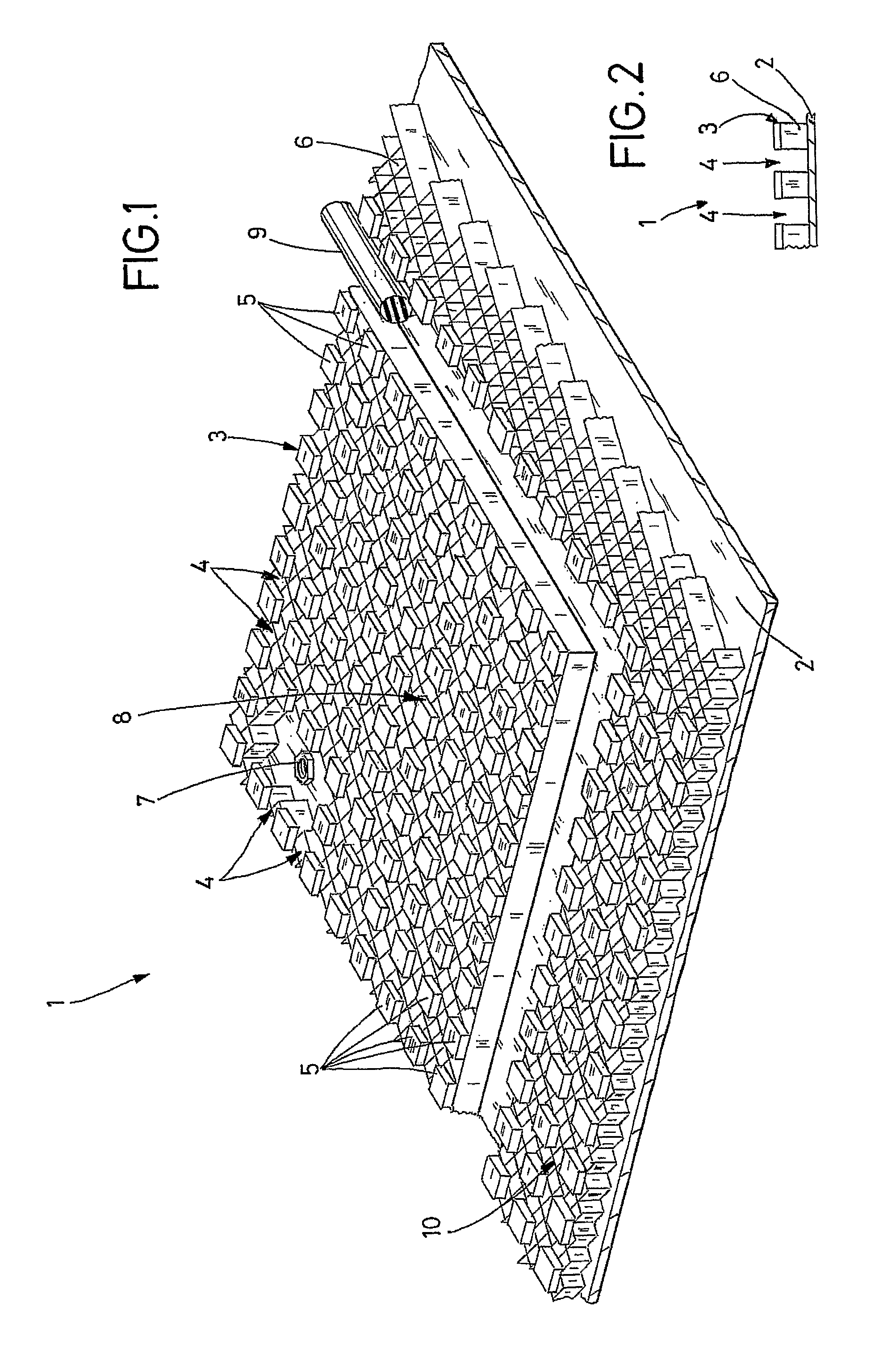
[0034]FIG. 1 is a perspective, partial cut-away view of a clamping plate 1 according to the invention. The clamping plate 1 has three layers: a first outer layer 2 that is designated a back layer, a second outer layer 3 that is designated a contact layer, and an intermediate layer 6 sandwiched between the two outer layers. The contact layer 3 is the layer that is brought into contact with a workpiece that is to be machined. The back layer 2 is shown as a single-piece, continuous layer that forms the back surface of a sandwich plate. The intermediate layer 6 is constructe...


PUM

PropertyMeasurementUnit
thicknessaaaaaaaaaa
inherent stiffnessaaaaaaaaaa
areaaaaaaaaaaa

Abstract

The invention is a clamping plate used to stiffen and hold a large, thin workpiece having low inherent stiffness. The clamping plate has a back layer, an intermediate layer and a contact layer. A plurality of grooves, which serve as air channels, is provided in the contact layer and the intermediate layer impart flexibility to the clamping plate. The clamping plate has sufficient flexibility to adapt to the specified contour of the workpiece. The contact layer is placed against the workpiece and vacuum apparatus provides suction through the air channels, which are in flow communication with each other between the two layers, to hold the workpiece against the clamping plate. One or more seals defines a holding area on the contact layer and prevent loss of suction.

Description

BACKGROUND INFORMATION[0001]1. Field of the Invention[0002]The invention relates to a device for stiffening a large, thin workpiece having low inherent stiffness. More particularly, the invention relates to a fixture for holding such a workpiece during a machining operation.[0003]2. Discussion of the Prior Art[0004]When machining large, thin aluminum sheets, for example, it is desirous to reduce the weight of the workpiece and this is commonly done by machining, i.e., milling, away material, so as to reduce the layer thickness in certain areas. This is commonly done in the field of aircraft construction. It is, of course, important to maintain high machining accuracy and avoid undesirable degradation of the components resulting from removing too much material. To this end, it is necessary to guide the machining tool, e.g., a cutter head, as precisely as possible, whereby the precise position of the workpiece also has to be maintained. Any flexibility in the workpiece can cause it to...

Claims


Application Information

Patent Timeline
Patent Type & Authority Patents(United States)
IPC IPC(8): B23Q3/08B25B11/00B65G47/91B23Q3/00
CPCB23Q3/088B65G47/91B25B11/005Y10T29/49998Y10T29/49774
Inventor JACOB, THOMASPIERICK, HANS-JURGENLOTTERT, RICHARD
Owner FOOKE GMBH
Why Eureka
Try Eureka