Method and apparatus for cutting glass sheets

Pending Publication Date: 2022-03-17
SCHOTT AG
View PDF0 Cites 0 Cited by
  • Summary
  • Abstract
  • Description
  • Claims
  • Application Information

AI Technical Summary

Benefits of technology

The patent describes a way to control the movement of a crack in a thin glass sheet. By using a special technique, the crack can move from one filament to the next without causing damage or becoming uncontrolled. This allows for better control over the direction of the crack and can improve the overall quality of the glass sheet.

Problems solved by technology

On the other hand, diamonds, as scoring tools, are very sensitive and can be damaged especially when placed on the glass.
These processes are generally unstable for thin glasses, since it is difficult to build up a sufficiently large temperature gradient between the top and bottom of the glass.
Furthermore, even the smallest temperature gradients lead to unstable three-dimensional distortions (“humps”).
In particular with thin substrates, however, there is the problem that a glass substrate whose strength has already been weakened by the perforation can be separated in an undefined manner during handling (e.g. transport).
As a result, the separation can take place in an uncontrolled manner with regard to the edge contour and, as a result, may also result in reduced edge strength.
The reason is that thin glass, due to its low inherent stiffness, tends to deform under the forces of handling and thus inadvertently higher tensile stresses can be inserted than required for cutting.
In particular, if these stresses do not act along the pre-prepared line, but deviate at an angle to it, uncontrolled breakage or reduced edge strength may occur.
Thereby, due to the focusing, the light intensity of the laser beam inside the glass sheet may become high enough that the laser beam leaves a filamentary damage along its path through the glass sheet.

Method used


Image

  • Method and apparatus for cutting glass sheets
  • Method and apparatus for cutting glass sheets
  • Method and apparatus for cutting glass sheets

Examples


Embodiment Construction

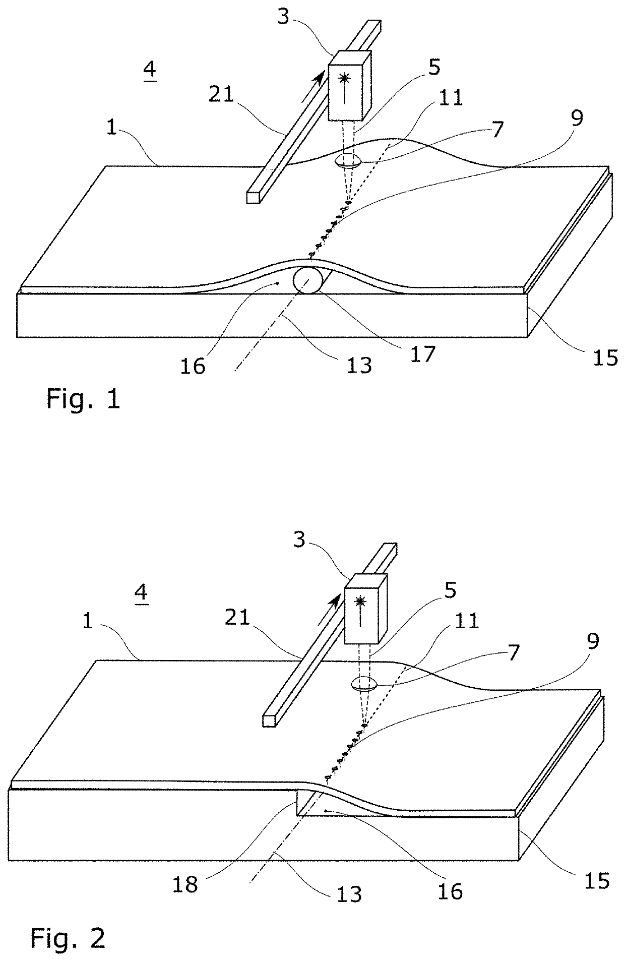
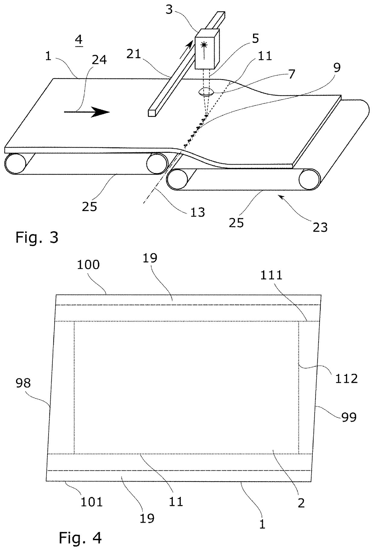
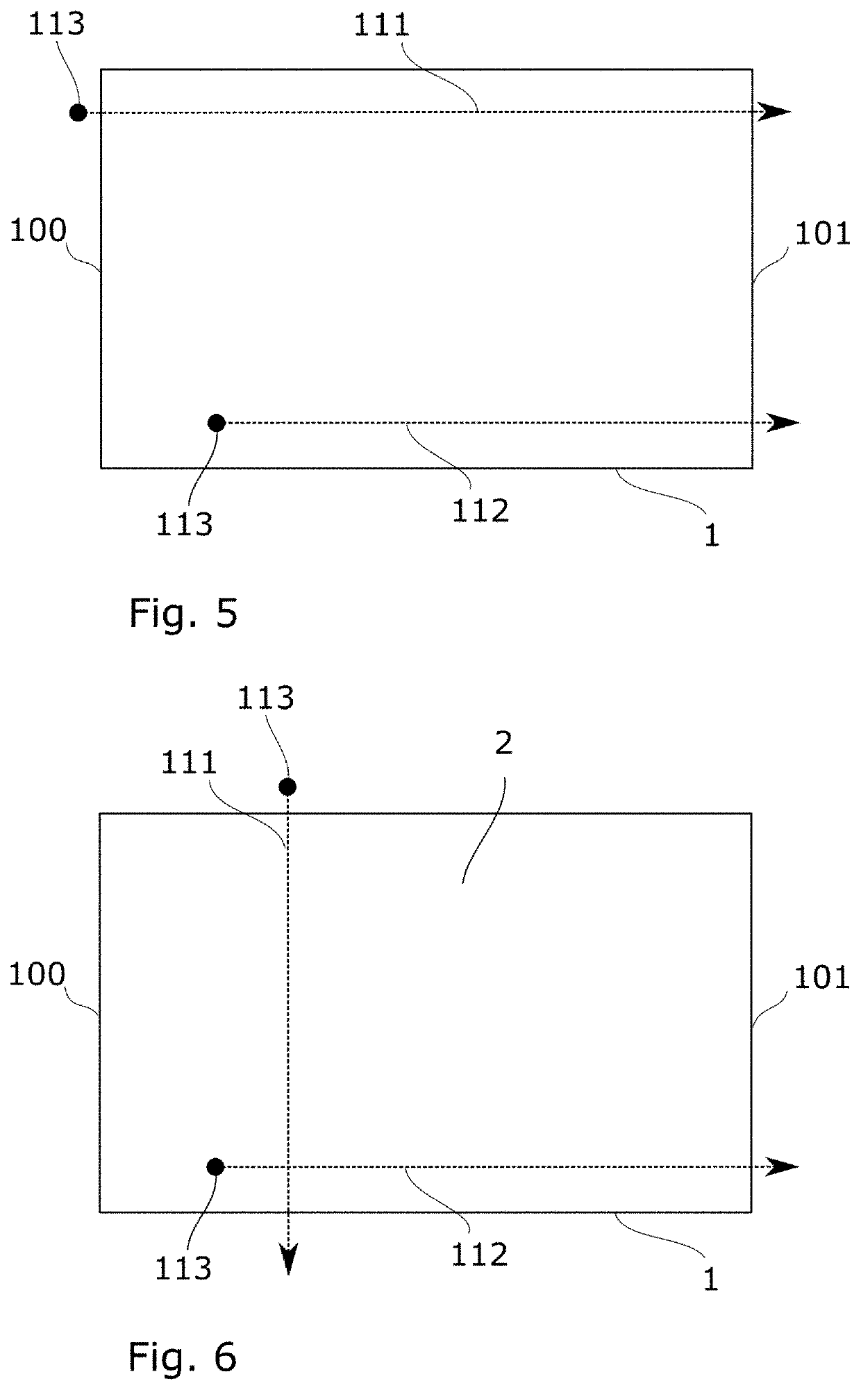
[0030]In FIG. 1 an apparatus 4 for carrying out the method described herein is shown. In general, without being restricted to the specific example shown, the apparatus 4 for separating glass sheets 1 with a thickness of at most 300 μm, comprises an ultrashort pulse laser 3 for irradiating a glass sheet 1 with a pulsed laser beam 5, wherein the laser beam 5 has a wavelength for which the glass is transparent, so that the laser beam 5 can traverse the glass sheet 1, as well as a focusing optics 7 to focus the laser beam 5, so that the light intensity of the laser beam 5 inside the glass sheet 1 becomes so high that the laser beam 5 leaves a filamentary damage 9 along its path through the glass sheet 1, and a device 21 to move the laser beam 5 and glass sheet 1 relative to each other, such that the pulses of the laser beam 5 insert filamentary damages 9 next to one another along a path 11 running on the glass sheet 1, as well as a device for exerting tensile stress on the glass sheet 1...


PUM

PropertyMeasurementUnit
Thicknessaaaaaaaaaa
Lengthaaaaaaaaaa
Tensile stressaaaaaaaaaa

Abstract

A method is provided that includes providing a glass sheet of a thickness of at most 300 μm and irradiating the glass sheet with a pulsed laser beam. The laser beam has a light intensity inside the glass sheet leaves a filamentary damage along its path through the glass sheet. The laser beam and the glass sheet are moved relative to each other so that due to the pulses of the laser beam filamentary damages are inserted next to one another along a path running on the glass sheet. During the insertion of the filamentary damages, a tensile stress is applied on the glass at the filamentary damages and in the direction transverse to the path of the adjacent filamentary damages so that the glass sheet separates along the path during insertion of the filamentary damages.

Description

CROSS REFERENCE TO RELATED APPLICATIONS[0001]This application claims benefit under 35 USC § 119 of German Application No. 10 2020 123 928.9 filed Sep. 14, 2021, the entire contents of which are incorporated herein by reference.BACKGROUND1. Field of the Invention[0002]The invention generally relates to the cutting of thin glasses. In particular, the invention relates to a method and an apparatus for cutting glasses with laser irradiation.2. Description of Related Art[0003]Separation of thin glass is standardly carried out with conventional scoring and breaking processes. These processes have at least two stages. First, a scratching tool, such as a scratching wheel or a diamond, is used to insert a superficial damage and subsequently the glass pane is separated along the superficial damage by mechanical bending or the introduction of thermomechanical stresses, for example by means of a CO2 laser.[0004]A cutting process in which a crack is inserted using a diamond or a similarly shaped...

Claims


Application Information

Patent Timeline
IPC IPC(8): C03B33/02C03B33/023C03B33/033C03B33/03B23K26/00B23K26/53B23K26/0622
CPCC03B33/0222C03B33/0235C03B33/033C03B33/03B23K2103/54B23K26/53B23K26/0624C03B2225/02B23K26/0006B23K26/08B23K26/70C03B33/023
Inventor WASCHBÜSCH, MICHAELPLAPPER, VOLKERKUREK, KLAUS-PETERENGELHARDT, ULRICH
Owner SCHOTT AG
Why Eureka
Try Eureka