Speaker unit and speaker unit mounting structure

a speaker unit and mounting structure technology, applied in the field of speaker units, can solve the problems of poor operability, the speaker unit can not be easily pulled out of the mounting hole of the ceiling, etc., and achieve the effect of improving the mounting structure of the speaker unit, reducing the number of necessary components, and simple construction

Active Publication Date: 2014-12-02
YAMAHA CORP
View PDF40 Cites 13 Cited by
  • Summary
  • Abstract
  • Description
  • Claims
  • Application Information

AI Technical Summary

Benefits of technology

[0005]In view of the foregoing prior art problems, it is an object of the present invention to provide an improved speaker unit and an improved speaker unit mounting structure which, with a simple construction of a minimized number of necessary component parts, allows the speaker unit to be released from a provisionally fastened state through only a simple operation performed from the face side of a mounting part.

Problems solved by technology

However, with the provisionally fastening structure disclosed in the relevant patent literature, once the speaker unit is provisionally fastened with the end portions of the resilient piece abutted against the reverse side of the ceiling around the outer periphery of the mounting hole, the abutting engagement of the resilient piece with the ceiling cannot be canceled by only an ordinary operation performed by a speaker-mounting human operator from the face side (lower side) of the ceiling, and thus, the provisionally fastened speaker unit cannot be readily pulled out from the mounting hole of the ceiling.
Thus, when the provisionally fastened speaker unit is to be detached for some reason in a speaker unit mounting operation, or when the speaker unit placed in the provisionally fastened position or state after having been released from the fully fixed or fastened state is to be pulled out of the mounting hole of the ceiling in a speaker unit dismounting operation, a disadvantage of poor operability would be encountered.

Method used


Image

  • Speaker unit and speaker unit mounting structure
  • Speaker unit and speaker unit mounting structure
  • Speaker unit and speaker unit mounting structure

Examples


Embodiment Construction

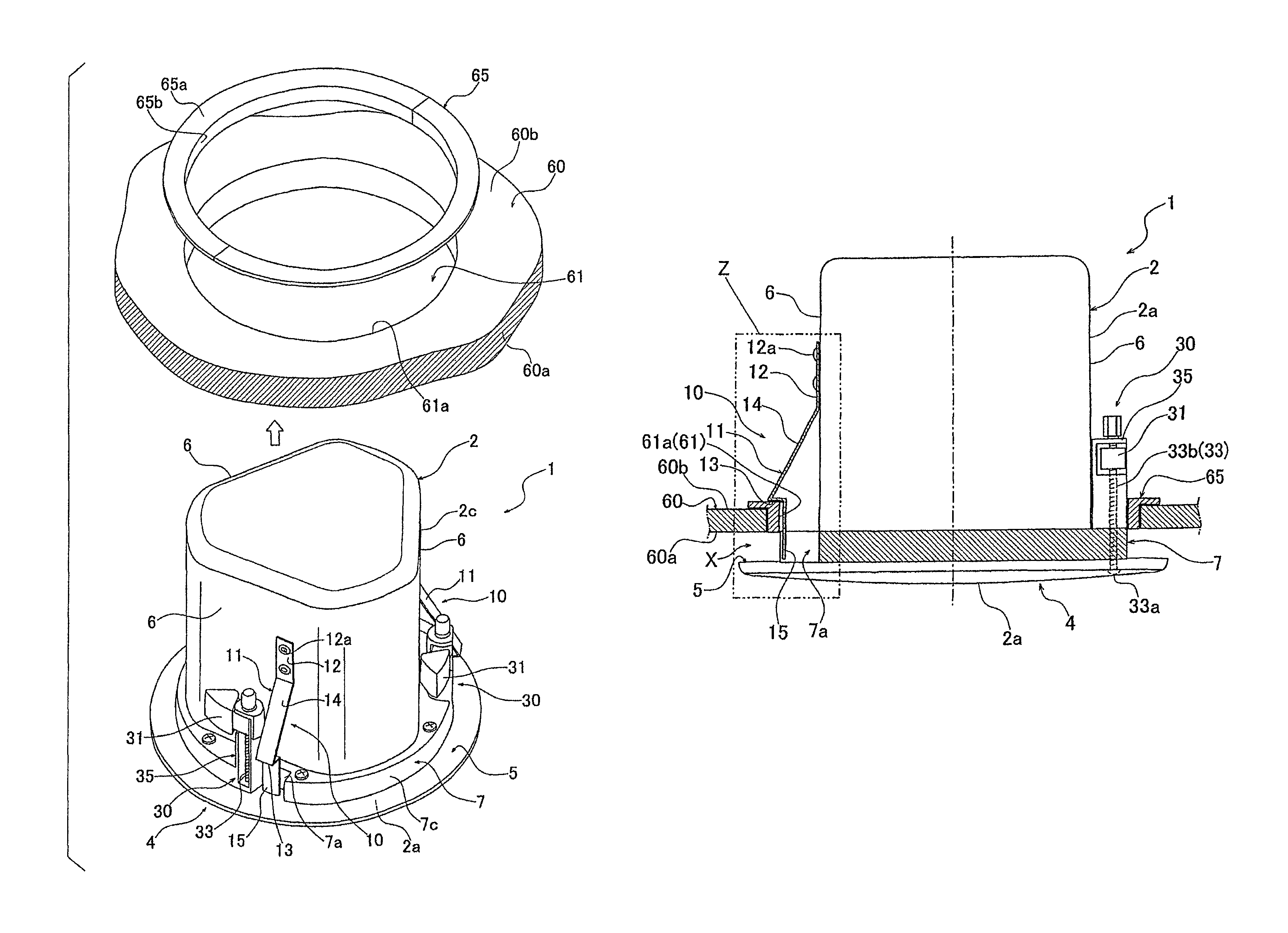
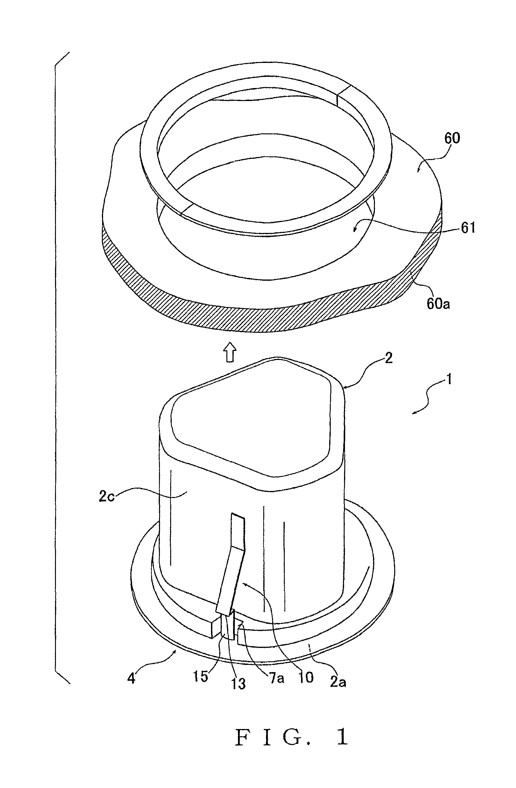
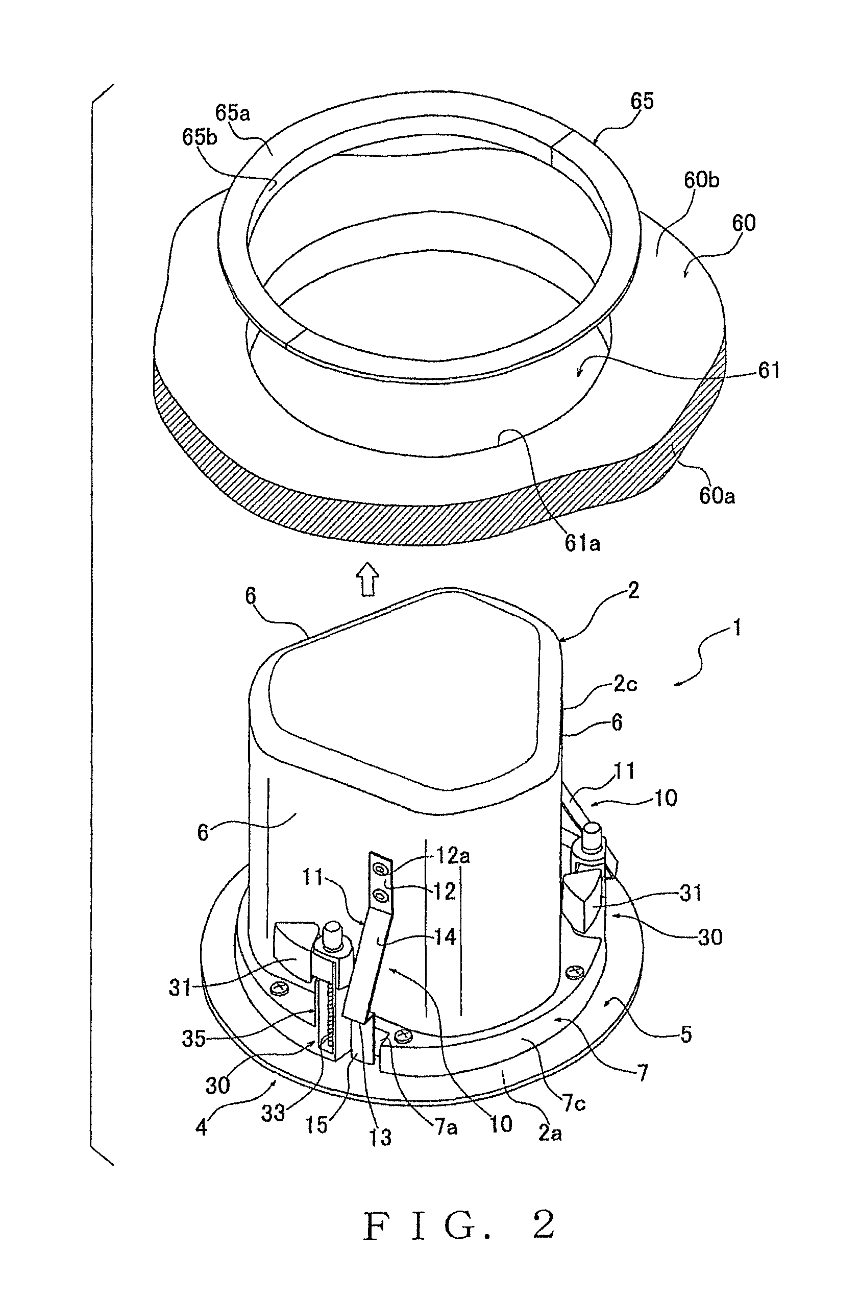
[0028]The following describe preferred embodiments of the present invention with reference to the accompanying drawings. FIG. 1 is a perspective view schematically showing a preferred embodiment of a speaker unit according to the present invention along with an embodiment of a mounting hole in which the speaker unit is to be mounted. A speaker unit 1 has a construction suitable to be mounted in an opening section 61 formed in a mounting part 60 such as a ceiling. The speaker unit 1 comprises: a cabinet section 2 having an outer peripheral side surface 2c and a bottom surface 2a; and a speaker face 4 provided on the bottom surface 2a of the cabinet section 2. The speaker unit 1 further comprises a provisionally fastening mechanism 10 which is provided on the outer peripheral side surface 2c of the cabinet section 2 and adapted to provisionally fasten the speaker unit 1 with at least a part of the cabinet section 2 inserted in the opening section 61 from a face side 60a of the mountin...


PUM


Abstract

A speaker unit mounting structure includes a provisionally fastening mechanism for fastening a speaker unit to a ceiling with a cabinet section of the speaker unit inserted in a mounting hole of the ceiling. The provisionally fastening mechanism includes a provisionally fastening tab formed of resilient metal, fixed to the outer peripheral side surface of the cabinet section and having a stepped engaging section engageable with the inner peripheral edge portion of the mounting hole. Engagement of the engaging section with the inner peripheral edge portion of the mounting hole can be canceled by a human operator pressing, from the face side of the ceiling, an operating section of the tab, exposed to a gap between the front side and a flange portion of the speaker unit, to thereby resiliently deform the operating section.

Description

BACKGROUND[0001]The present invention relates to a speaker unit adapted to be embedded in an opening section formed in a mounting part, such as a ceiling or side wall, and also relates to a structure for installing or mounting the speaker unit by embedding it in the opening.[0002]There have heretofore been known embedded-type speaker units (such as ceiling speakers) that are installed or mounted by being embedded in a mounting hole (opening section) formed in a ceiling or the like of a room, as disclosed for example in Japanese Patent Application Laid-open Publication No. 2004-120192 (hereinafter referred to as “the relevant patent literature”). Generally, such a speaker unit includes a cabinet section of a substantially cylindrical shape, and a speaker face provided on the bottom surface of the cabinet section. To mount the speaker unit, the cabinet section is inserted into a mounting hole of the ceiling with the speaker face exposed on the face (i.e., lower surface) of the ceiling...

Claims


Application Information

Patent Timeline
Patent Type & Authority Patents(United States)
IPC IPC(8): F21V21/088H04R1/00B42F13/00H04R1/02F21V21/08B42F13/02
CPCH04R1/026H04R2201/021
Inventor TANAKA, KATSUYAMIZUNO, KOTARO
Owner YAMAHA CORP
Why Eureka
Try Eureka