
Apparatus and method of energy efficient illumination using received signals

a technology of received signals and apparatuses, applied in the direction of discharge tubes/lamp details, electric discharge lamps, discharge tubes/lamp details, etc., can solve the problems of low energy efficiency of lighting systems between late evening and early morning hours, and achieve the effect of improving the energy efficiency of lighting systems

Active Publication Date: 2014-12-02
EXPRESS IMAGING SYST
View PDF144 Cites 64 Cited by
  • Summary
  • Abstract
  • Description
  • Claims
  • Application Information

AI Technical Summary

Benefits of technology

[0011]As previously explained, lighting systems which use dusk-to-dawn control mechanisms typically provides light at a continuous, relatively high, level from dusk to dawn. The exception to such appears to be when motion or proximity based sensing is included in such a control mechanism. In many instances, a high level of lighting or illumination is not necessary throughout the entire period. For instance, in retail business or corporate office parking lots high levels of light or illumination are typically only useful into the late evening hours (e.g., 10 PM or 11 PM) and early morning hours (e.g., 4 AM or 5 AM). High level lighting or illumination between the late evening and early morning hours provide little benefit. A lower level of light or illumination during such hours may achieve sufficient illumination for some desired purpose (e.g., security), while reducing energy consumption. Such may useful with a simple dusk-to-dawn control mechanism. Use of a low level lighting or illumination during such hours may also make practical use of relatively slow warm up light sources with motion or proximity based control mechanisms since the illumination sources may only need to be warmed up from an already turned ON, but reduced output state, instead of warming up from an OFF state.
[0012]Illumination systems may be used in secured environments or in situations where security is important. Thus, it would be particular advantageous if the lighting control mechanism of the illumination system is designed to handle unintentional conditions, for example the failure of a component such as an ambient light sensor. It would also be particularly advantageous if the lighting control mechanism of the illumination system is designed to handle intentional tampering, for example tampering in the form of shining focused light on a light sensor in an attempt to prevent illumination of a surrounding area by the lighting system. It would additionally be advantageous if the lighting control system continued to operate as programmed even if a component failed, for example even if a light sensor failed. It may further be advantageous if the lighting control mechanism did not require extensive training, learning or adjustment to the existing ambient environmental conditions. For instance, it would be advantageous if the lighting control system could quickly adjust to the daily cycle (e.g., solar noon, solar midnight) for the particular geographic location at which the illumination system is installed, without the need to first obtain samples over multiple days or even weeks. It would be very advantageous if the lighting control system automatically determined the local time of day for a particular geographic location at which the illumination system is installed. Such would allow lighting levels to be programmed to coincide with local activity such a retail store business hours. Such local activity typically occurs at fixed hours, regardless of the length of day or seasonal changes in length of day. For example, it would be advantageous to turn the lighting system to a high level of illumination at dusk, and reduce the output to a lower level of illumination at a fixed time of day (e.g., 10 PM local time).

Problems solved by technology

High level lighting or illumination between the late evening and early morning hours provide little benefit.

Method used


Image

  • Apparatus and method of energy efficient illumination using received signals
  • Apparatus and method of energy efficient illumination using received signals
  • Apparatus and method of energy efficient illumination using received signals

Examples


Embodiment Construction

[0043]In the following description, certain specific details are set forth in order to provide a thorough understanding of various disclosed embodiments. However, one skilled in the relevant art will recognize that embodiments may be practiced without one or more of these specific details, or with other methods, components, materials, etc. In other instances, well-known structures associated with luminaires and imaging devices have not been shown or described in detail to avoid unnecessarily obscuring descriptions of the embodiments.

[0044]Unless the context requires otherwise, throughout the specification and claims which follow, the word “comprise” and variations thereof, such as, “comprises” and “comprising” are to be construed in an open, inclusive sense that is as “including, but not limited to.”

[0045]Reference throughout this specification to “one embodiment” or “an embodiment” means that a particular feature, structure or characteristic described in connection with the embodim...


PUM


Abstract

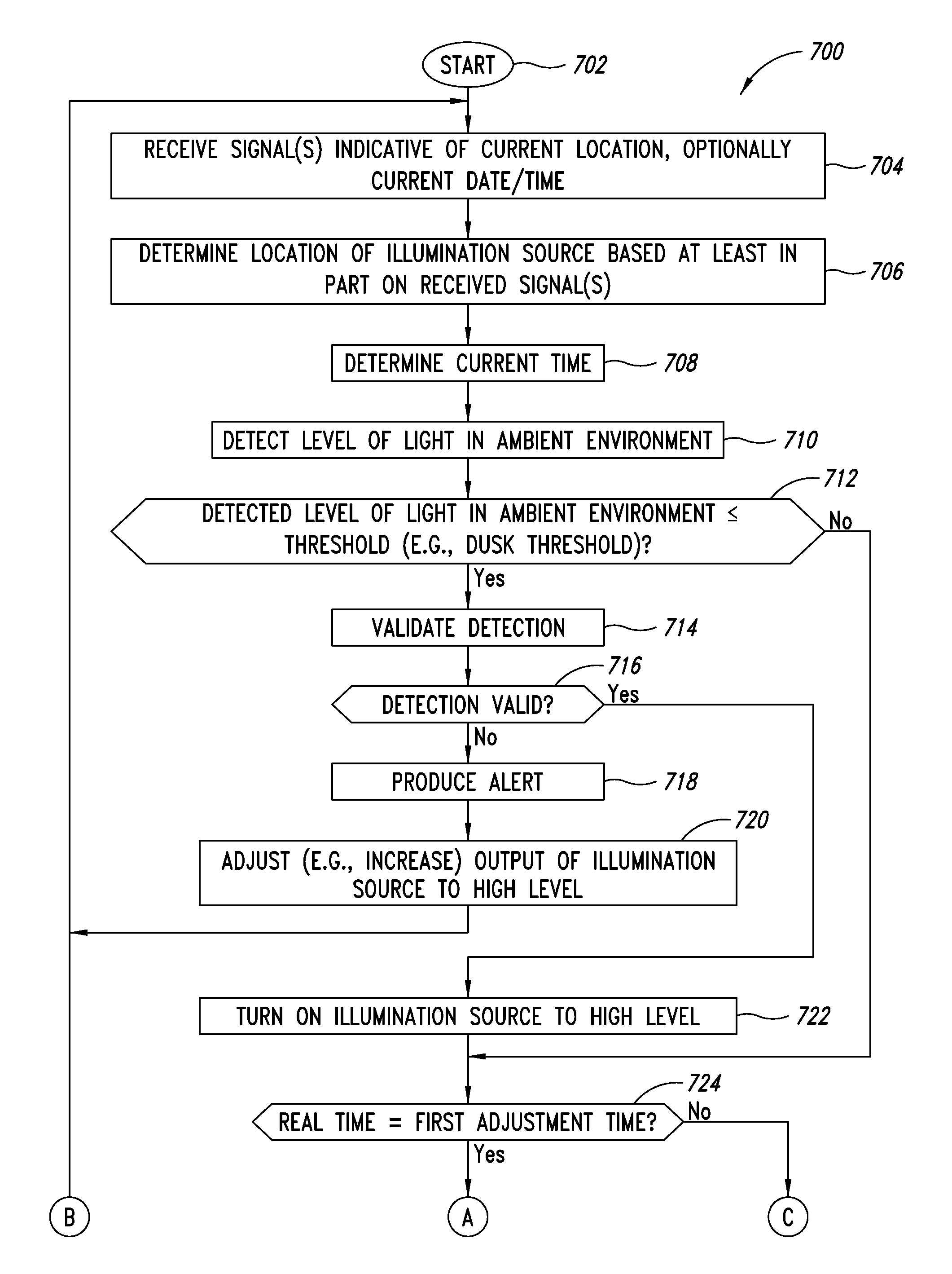
Illumination sources are turned ON and turned OFF in response to detected levels of illumination in an ambient environment reaching respective thresholds, which may be user set. The detection of these turn ON and turn OFF events is verified, for instance against expected events or conditions for the particular location, date and / or time. An alert or log entry may be generated if a detected event or condition appears to be invalid. For instance, if an amount of illumination in the environment is different than predicted by a threshold amount or if a time that the event occurs or is detected is different than expected or predicted by more than a threshold amount. A level of illumination may be decreased to some non-zero level after a specified time after turn ON, and increased at some specified time before turnOFF. Use of information from external sources (e.g., satellites, cell towers) may allow times to be using local time, including daylight savings if applicable.

Description

BACKGROUND[0001]1. Technical Field[0002]The present disclosure generally relates to the field of illumination devices and, more particularly, to control of illumination to improve energy efficiency and security.[0003]2. Description of the Related Art[0004]Energy conservation has become of ever increasing importance. Efficient use of energy can result in a variety of benefits, including financial benefits such as cost savings and environmental benefits such as preservation of natural resources and reduction in “green house” (e.g., CO2) gas emissions.[0005]Residential, commercial, and street lighting which illuminate interior and exterior spaces consume a significant amount of energy. Conventional lighting devices or luminaires exist in a broad range of designs, suitable for various uses. Lighting devices employ a variety of conventional light sources, for example incandescent lamps, florescent lamps such as high-intensity discharge (HID) lamps (e.g., mercury vapor lamps, high-pressur...

Claims


Application Information

Patent Timeline
Patent Type & Authority Patents(United States)
IPC IPC(8): H05B37/02
CPCH05B37/0218Y02B20/44Y02B20/46H05B37/0245H05B37/0227H05B47/11H05B47/16H05B47/105Y02B20/40H05B47/115H05B47/19H05B47/175
Inventor REED, WILLIAM G.
Owner EXPRESS IMAGING SYST
Learn More