Apparatus and method to accommodate changes in communication quality

a transmission apparatus and image data technology, applied in the field of transmission apparatus and transmission method for wirelessly transmitting image data, can solve the problems of frequent switching image flicker, subjective image quality deterioration, etc., to achieve the effect of reducing the flickering of an image, reducing the transmission rate of the transmission apparatus, and improving subjective image quality

Inactive Publication Date: 2014-12-02
SONY CORP
View PDF4 Cites 0 Cited by
  • Summary
  • Abstract
  • Description
  • Claims
  • Application Information

AI Technical Summary

Benefits of technology

[0010]In view of the circumstances as described above, there is a need for a transmission apparatus and a transmission method that are capable of suppressing flickering of a display image on a reception side that accompanies a change in an image transmission rate and thus improving a subjective image quality.
[0012]According to the embodiment of the present invention, the control section controls the image transmission rate within the first response time when lowering it and controls the image transmission rate within the second response time longer than the first response time when raising it. Thus, it is possible to suppress flickering of an image accompanying a frequent change of the image transmission rate in a display image on a reception side and improve a subjective image quality.
[0013]More specifically, the control section may control the image transmission rate of the encode section to be raised at a time point a period during which the wireless transmission rate is higher than the image transmission rate has continued a certain period. Moreover, the control section may raise the image transmission rate stepwise toward the current image transmission rate every time the certain period passes when raising the image transmission rate. With this structure, flickering of an image when viewed by a viewer at the time the image transmission rate is switched can be additionally suppressed. In addition, since a time during which a low image transmission rate is used becomes that much shorter, deterioration of the subjective image quality can be suppressed.
[0014]The certain period is desirably 0.3 second to 1 second considering responsiveness of human eyesight to a temporal contrast change and chromaticity change. As a result, flickering of an image can be additionally suppressed.
[0015]According to the embodiment of the present invention, it is possible to suppress flickering of a display image on a reception side that accompanies a change in an image transmission rate and thus improve a subjective image quality.

Problems solved by technology

However, in an environment in which a wireless communication quality changes frequently, the image transmission rate of the transmission apparatus switches frequently.
In this case, luminance and chromaticity of a display image on a reception apparatus side frequently change at a time the image transmission rate is switched, with the result that an image may flicker when viewed by a viewer and a subjective image quality may deteriorate.
Moreover, in a case where a technique called beam forming with which a direction of beams can be controlled after a directivity of the beams is narrowed so that radio waves reach the reception side efficiently is introduced or high bandwidth radio waves of, for example, 60 GHz that have high linearity is used, the communication quality fluctuates by a trivial cause and deterioration of a subjective image quality due to flickering of a display image becomes prominent.
In this case, due to a slight change such as people moving in the room or a curtain being blown by a wind, the path changes to inadvertently change the communication quality.
Moreover, even when there is no moving object, if there are a plurality of paths in which an equivalent level of radio wave intensities can be obtained, the paths are switched frequently to thus destabilize the communication quality.
In this case, however, large-capacity reception buffers are required.

Method used


Image

  • Apparatus and method to accommodate changes in communication quality
  • Apparatus and method to accommodate changes in communication quality
  • Apparatus and method to accommodate changes in communication quality

Examples


Embodiment Construction

[0024]Hereinafter, an embodiment of the present invention will be described with reference to the drawings.

(Structure of Wireless Transmission System)

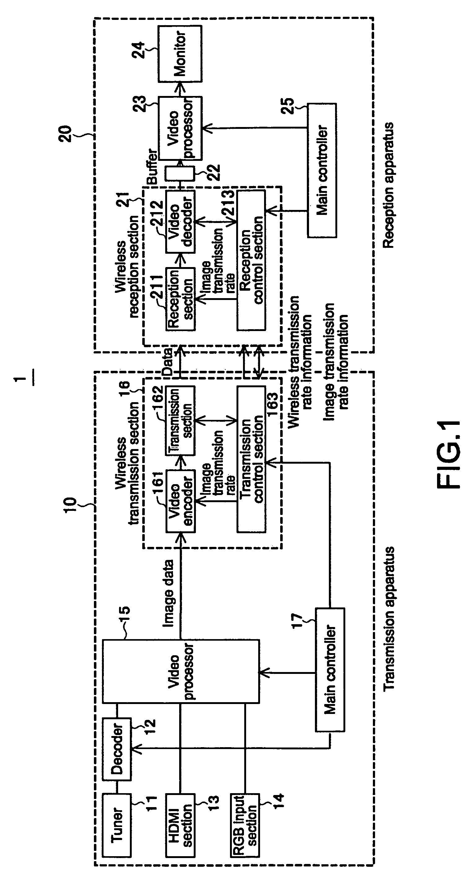
[0025]FIG. 1 is a diagram showing a structure of a wireless transmission system according to an embodiment of the present invention.

[0026]As shown in the figure, a wireless transmission system 1 is constituted of a transmission apparatus 10 and a reception apparatus 20. The transmission apparatus 10 is an apparatus that compression-codes image and audio data, modulates the data into a format suited for a wireless transmission, and transmits the modulated data using an antenna (not shown). The reception apparatus 20 is an apparatus that receives signals wirelessly transmitted from the transmission apparatus 10, restores the signals into an original image and audio through demodulation and decode, and outputs the data as a visible image and audible sound.

[0027]Here, the reception apparatus 20 is provided as, for example, a television rec...


PUM


Abstract

A transmission apparatus which may include an image encoder, a transmitter, and a controller. The apparatus may encode image data, wirelessly transmit the encoded image data, detect a quality of a wireless transmission of the encoded image data and control an image transmission rate based on the detected quality. The image transmission rate may be controlled within a first response time when being lowered and controlled within a second response time longer than the first response time when being raised.

Description

CROSS-REFERENCE TO RELATED APPLICATION[0001]The present application claims priority from Japanese Patent Application No. JP 2009-233936 filed in the Japanese Patent Office on Oct. 7, 2009, the entire content of which is incorporated herein by reference.BACKGROUND OF THE INVENTION[0002]1. Field of the Invention[0003]The present invention relates to a transmission apparatus and a transmission method for wirelessly transmitting image data.[0004]2. Description of the Related Art[0005]In a system that wirelessly transmits compression-coded image data, a transmission apparatus controls a transmission rate based on a communication quality that changes with time due to a change in a communication environment. In other words, the transmission apparatus raises the transmission rate when the communication quality is high and lowers the transmission rate when the communication quality is low. As a method of detecting a communication quality that changes due to a change in the communication envi...

Claims


Application Information

Patent Timeline
Patent Type & Authority Patents(United States)
IPC IPC(8): G06F3/147H04N19/166H04N7/12H04N19/61H04N21/4363H04N19/102H04L1/00H04N5/57H04N19/169H04N19/115H04L29/08H04N19/00H04N19/146H04N19/164H04N19/196H04N19/625H04N19/65H04N19/85H04N19/89
CPCH04N19/61G09G2370/12H04N19/166G06F3/147G09G2370/16H04N19/169H04N19/115H04L1/0014H04N19/102G09G2350/00H04N7/50H04N19/157G09G2340/02H04N5/57H04N21/43637H04L1/0015H04N19/127H04N7/52
Inventor NAGARA, TORUTAKEUCHI, FUTOSHIHORII, AKIHIROSATO, MASANORIANAMI, YUJI
Owner SONY CORP
Why Eureka
Try Eureka