Thermoelectric energy storage system with an intermediate storage tank and method for storing thermoelectric energy

a technology of thermoelectric energy storage and intermediate storage tank, which is applied in the field of storage of electric energy, can solve the problems of limited thermoelectric energy storage efficiency, loss of rest of electrical energy, and inherently limited round-trip efficiency of electric energy storage technologies

Active Publication Date: 2014-12-09
ABB (SCHWEIZ) AG
View PDF6 Cites 53 Cited by
  • Summary
  • Abstract
  • Description
  • Claims
  • Application Information

AI Technical Summary

Benefits of technology

[0004]In EP 1577548, the applicant has described the concept of a thermoelectric energy storage (TEES) system. A TEES converts excess electricity to heat in a charging cycle, stores the heat, and converts the heat back to electricity in a discharging cycle, when necessary. Such an energy storage system is robust, compact, site independent and is suited to the storage of electrical energy in large amounts. Thermal energy can be stored in the form of sensible heat via a change in temperature or in the form of latent heat via a change of phase or a combination of both. The storage medium for the sensible heat can be a solid, liquid, or gas. The storage medium for the latent heat occurs via a change of phase and can involve any of these phases or a combination of them in series or in parallel.

Problems solved by technology

However, it is important to point out that all electric energy storage technologies inherently have a limited round-trip efficiency.
The rest of the electrical energy is lost.
The efficiency of thermoelectric energy storage is limited for various reasons rooted in the second law of thermodynamics.
Firstly, the conversion of heat to mechanical work in a heat engine is limited to the Carnot efficiency.
Secondly, the coefficient of performance of any heat pump declines with increased difference between input and output temperature levels.
Thirdly, any heat flow from a working fluid to a thermal storage and vice versa requires a temperature difference in order to happen.
This fact inevitably degrades the temperature level and thus the capability of the heat to do work.
Problematically, these solutions result in a high capital cost and therefore are not generally practical.
Furthermore, even if relatively large heat exchangers are used, the thermodynamic properties of the working fluid act to limit the minimization of temperature differences.
In such an application, any increase of heat exchange temperature losses during charging and discharging directly translates to loss of useful work and reduction of the round trip efficiency of the system.

Method used


Image

  • Thermoelectric energy storage system with an intermediate storage tank and method for storing thermoelectric energy
  • Thermoelectric energy storage system with an intermediate storage tank and method for storing thermoelectric energy
  • Thermoelectric energy storage system with an intermediate storage tank and method for storing thermoelectric energy

Examples


Embodiment Construction

[0023]Exemplary embodiments of the present disclosure provide a thermoelectric energy storage system for converting electrical energy into thermal energy to be stored and converted back to electrical energy with an improved round-trip efficiency. Exemplary embodiments of the present disclosure provide a thermoelectric energy storage system and a method for storing and retrieving energy in a thermoelectric energy storage system.

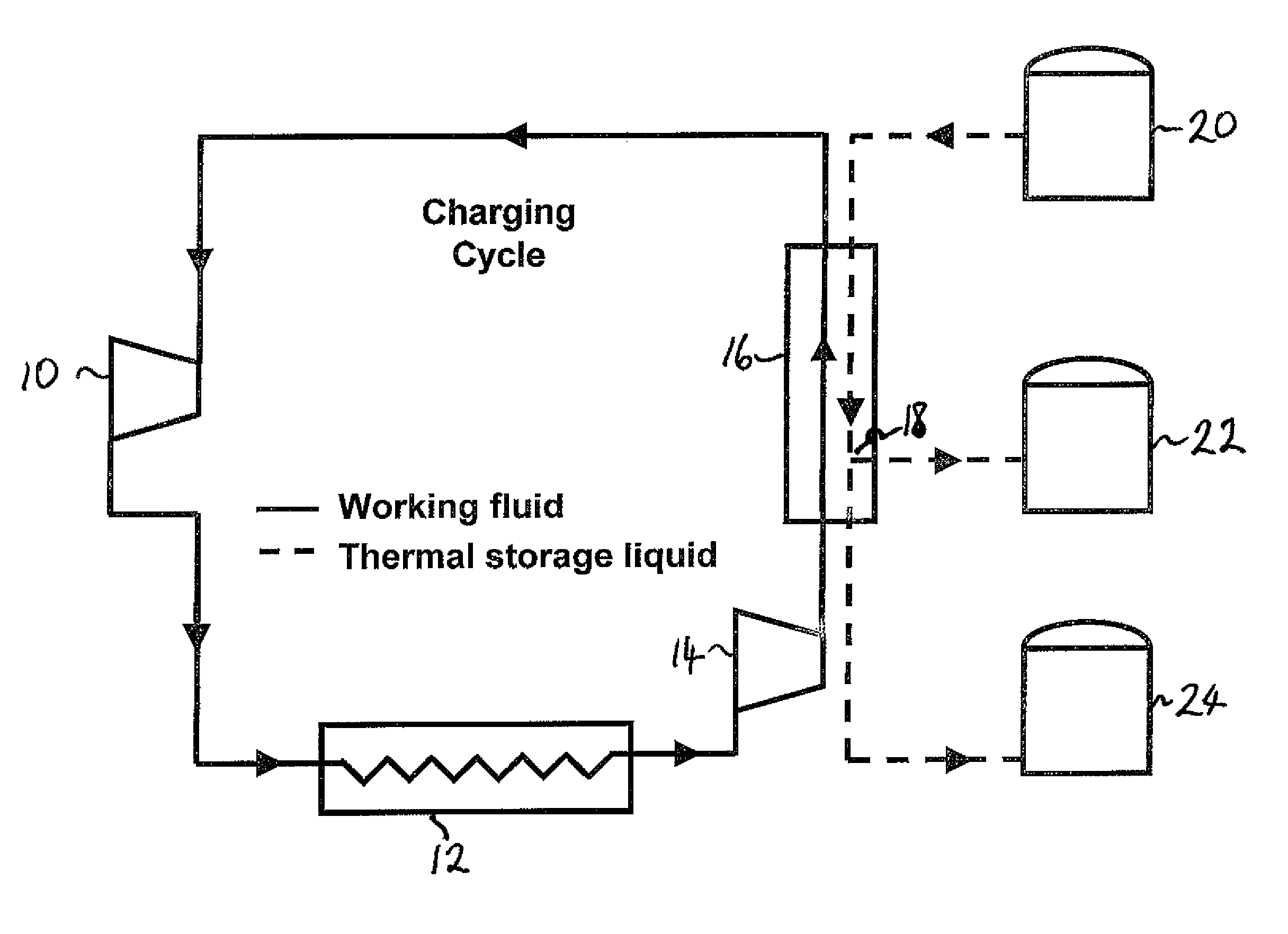
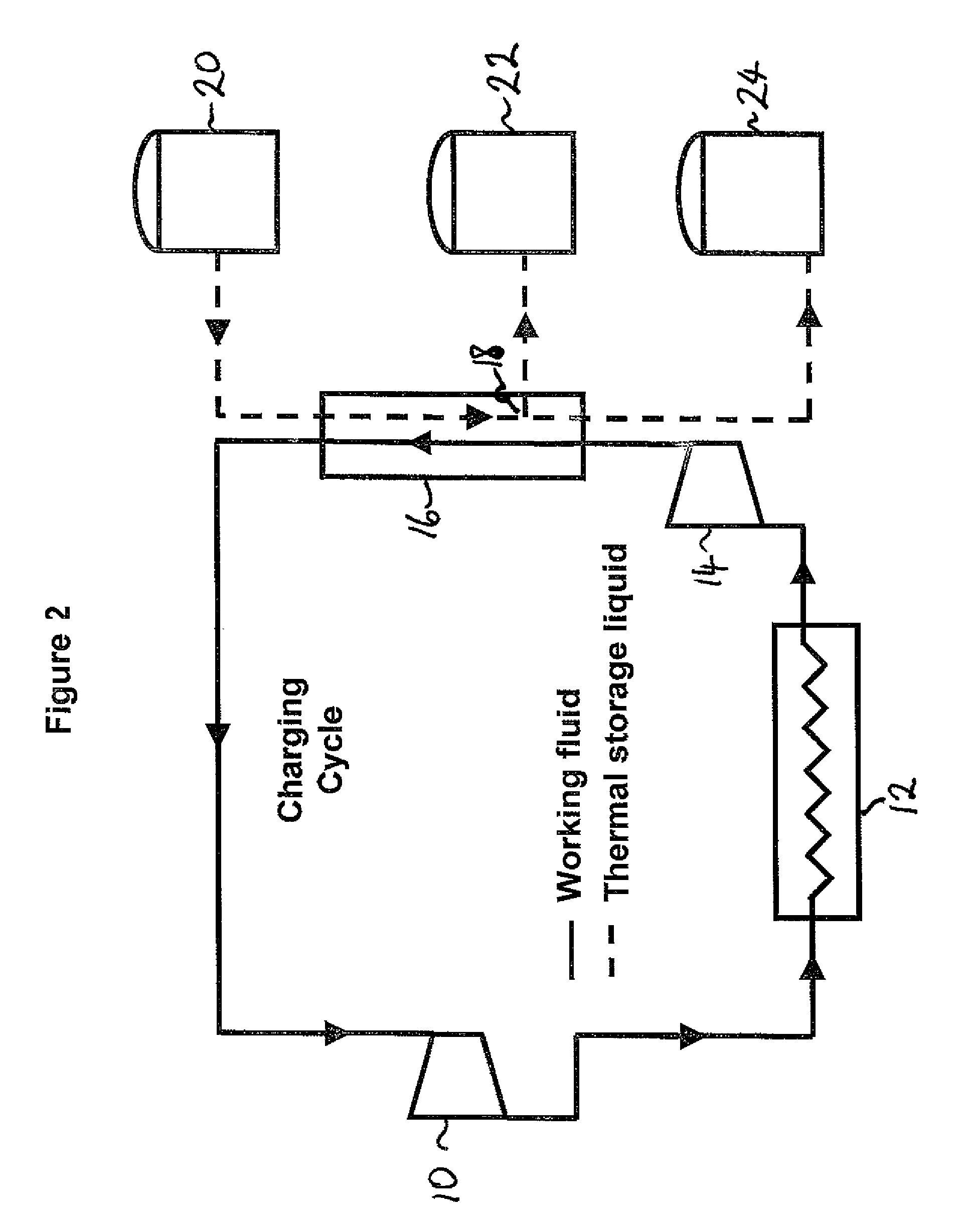
[0024]According to an exemplary embodiment of the present disclosure, a thermoelectric energy storage system has a charging cycle for providing thermal energy to a thermal storage, and a discharging cycle for generating electricity by retrieving the thermal energy from the thermal storage. The thermoelectric energy storage system includes a working fluid circuit for circulating a working fluid through a heat exchanger, and a thermal storage medium circuit for circulating a thermal storage medium. The thermal storage medium circuit includes at least one hot sto...


PUM


Abstract

A system and method are provided for storing electric energy in the form of thermal energy. A thermoelectric energy storage system includes a working fluid circuit for circulating a working fluid through a heat exchanger, and a thermal storage medium circuit for circulating a thermal storage medium. The thermal storage medium circuit includes at least one hot storage tank, an intermediate temperature storage tank, and a cold storage tank connected together via the heat exchanger. A proportion of the storage medium is redirected to or from the intermediate storage tank from or to the hot or cold storage tank, joining another proportion which flows directly between the cold and hot storage tank.

Description

RELATED APPLICATION[0001]This application claims priority as a continuation application under 35 U.S.C. §120 to PCT / EP 2010 / 057946, which was filed as an International Application on Jun. 8, 2010 designating the U.S., and which claims priority to European Application 09163084.8 filed in Europe on Jun. 18, 2009. The entire contents of these applications are hereby incorporated by reference in their entireties.FIELD[0002]The present disclosure relates generally to the storage of electric energy. More particularly, the present disclosure relates to a system and method for storing electric energy in the form of thermal energy in a thermal energy storage.BACKGROUND INFORMATION[0003]Base load generators such as nuclear power plants and generators with stochastic, intermittent energy sources, such as wind turbines and solar panels, generate excess electrical power during times of low power demand. Large-scale electrical energy storage systems are a means of diverting this excess energy to ...

Claims


Application Information

Patent Timeline
Patent Type & Authority Patents(United States)
IPC IPC(8): F28D20/00F01K1/00F28D20/02F01K3/12
CPCY02E60/142F28D20/00F01K3/12F28D20/0034F28D20/02F28D17/04F28D2020/0069F24S60/00F24S60/30F28D2020/0082Y02E10/40Y02E60/14Y10S165/902F01K1/08F01K3/08F01K3/14F22B1/028F28D20/0056F28D20/021F28D2020/0047Y02E70/30
Inventor HEMRLE, JAROSLAVKAUFMANN, LILIANMERCANGOEZ, MEHMET
Owner ABB (SCHWEIZ) AG
Why Eureka
Try Eureka