Low-slung electric vehicle

a low-slung electric vehicle and electric motor technology, applied in the field of low-slung electric vehicles, can solve the problems of increasing the unit and the difficulty of replacing the battery unit, and achieve the effect of preventing the operator from rattling the mounted battery unit, facilitating the operation of mounting and removing, and preventing the operator from rattling

Inactive Publication Date: 2014-12-09
HONDA MOTOR CO LTD
View PDF25 Cites 42 Cited by
  • Summary
  • Abstract
  • Description
  • Claims
  • Application Information

AI Technical Summary

Benefits of technology

[0009]In this connection, an embodiment of the present invention provides a low-slung electric vehicle that is adapted not only to facilitate the operations of mounting and removing the battery unit but also to prevent the rattling of the mounted battery unit and that is also capable of preventing the operator from forgetting to disconnect the cable in removing the battery unit.

Problems solved by technology

However, the battery unit is increased in weight to thereby make it difficult to replace the battery unit.

Method used


Image

  • Low-slung electric vehicle
  • Low-slung electric vehicle
  • Low-slung electric vehicle

Examples


first embodiment

[0057]First, a first embodiment shown in FIG. 1 to FIG. 12 is described.

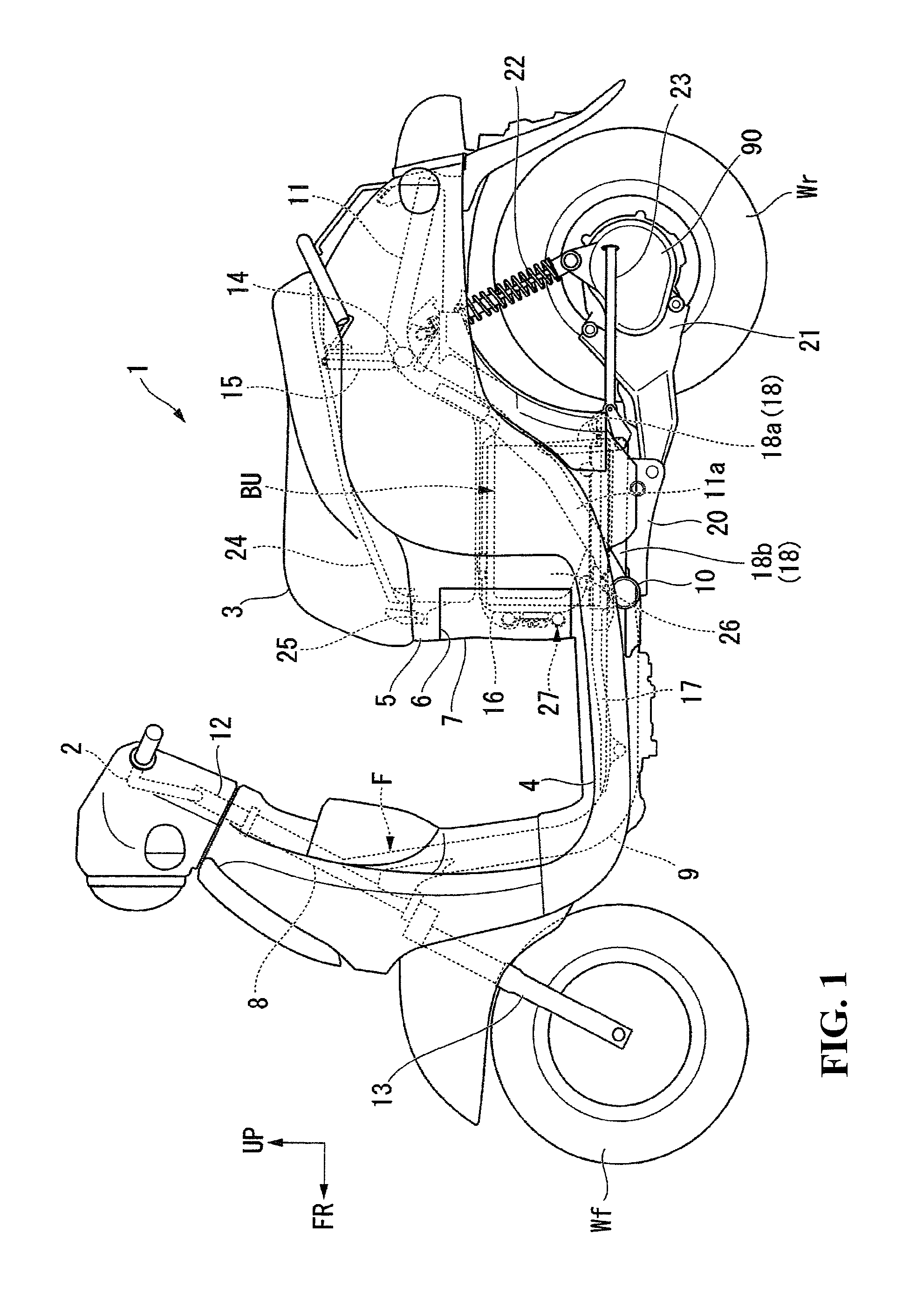
[0058]FIG. 1 is a side view showing the whole body of a vehicle of this embodiment.

[0059]The vehicle of this embodiment is a scooter-type two-wheeled electric vehicle 1 which represents one mode of a low-slung electric vehicle. The two-wheeled electric vehicle 1 is provided with a footrest floor 4 for an occupant's feet to rest on between a steering handlebar 2 and an occupant seat 3. The two-wheeled electric vehicle 1 has a rear wheel Wr driven by an electric motor 90. This two-wheeled electric vehicle 1 further includes a suspension system for a front wheel Wf and a suspension system for the rear wheel Wr which are supported forwardly and rearwardly of a body frame F, respectively. Further, the seat 3 is supported at an upper part substantially centrally of the body frame F in a fore-aft direction.

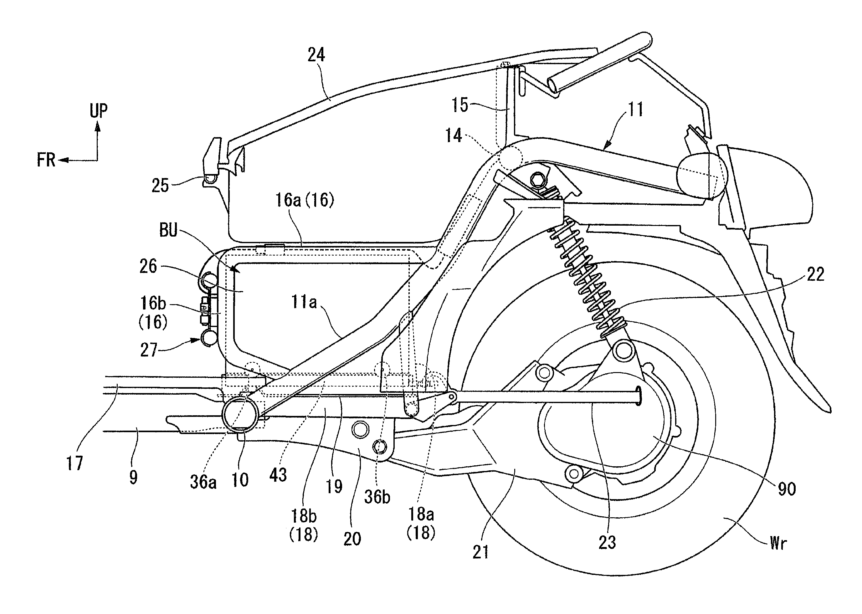
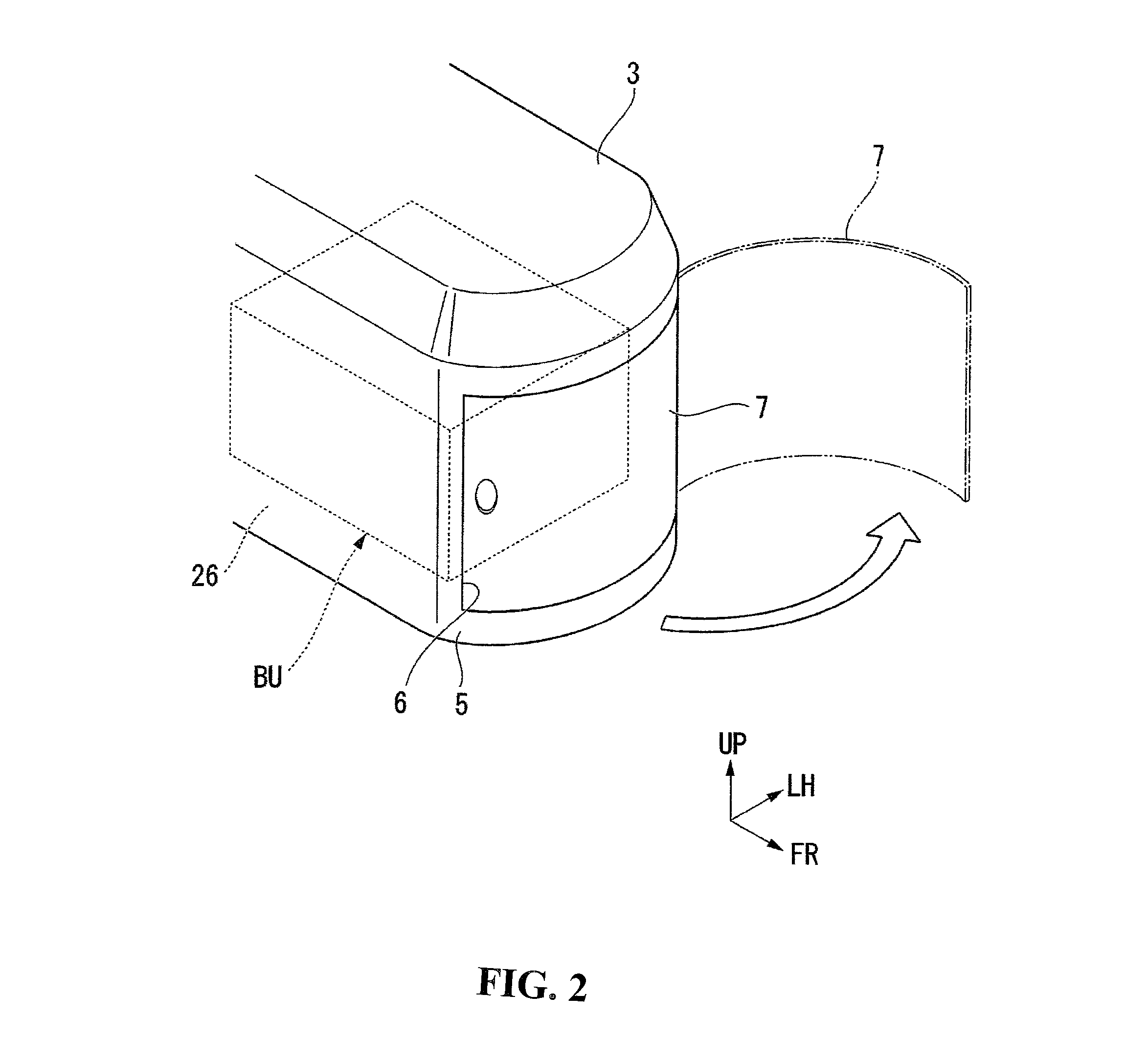
[0060]In this two-wheeled electric vehicle 1, a battery unit BU as a power supply of the vehicle is disposed in sp...

third embodiment

[0125]Next, a description is made on a third embodiment shown in FIG. 15 and FIG. 16.

[0126]This embodiment adds another structure for preventing the rattling of the battery unit BU relative to the structure of the first embodiment or the second embodiment.

[0127]A vehicle of this embodiment includes a hook portion 58 for locking and fixing a rear end of the battery unit BU. The hook portion 58 is integrally formed at an upper end of the main stand 23 for allowing the parked vehicle to stand. A flange 59 projects from a lower edge of the rear end of the battery unit BU. The flange 59 is formed with a locking hole 60. The locking hole 60 is equipped with an annular elastic member 61 formed of rubber or soft resin.

[0128]With the main stand 23 set on the ground, the hook portion 58 extends upwardly from a pivot 62 of the vehicle body, as shown in FIG. 16. When the main stand 23 in this position is kicked up, as shown in FIG. 15, the hook portion 58 rotates about the pivot 62 to a front l...

fourth embodiment

[0133]Lastly, a description is made on the invention shown in FIG. 17 to FIG. 19.

[0134]This embodiment is constructed the same way as the first embodiment and the second embodiment in that the battery unit BU is provided with the guide grooves and the rolling rollers while the guide rails are provided on the floor plate of the battery compartment, that the recesses for the rolling rollers to drop into are formed on the guide rails, and that the lower side of the battery unit BU and the upper side of the floor plate are formed with the engaging projections and the engagement holes adapted for fitting with each other. However, this embodiment differs from the first embodiment and the second embodiment in the structure and location of an electrode connector 142 and a feeder connector 141.

[0135]More specifically, the battery unit BU has the electrode connector 142 projecting rearwardly from a rear end face thereof. This electrode connector 142 is integrally fixed to the rear end face of...


PUM


Abstract

A low-slung electric vehicle that facilitates the operation of mounting and removing a battery unit while also preventing the rattling of the mounted battery unit. In addition, the battery unit is capable of preventing an operator from forgetting to disconnect a cable when removing the battery unit. A battery unit is provided with rolling rollers. Recesses are formed in upper sides of guide rails to accommodate the rolling rollers to permit the rolling rollers to drop therein when the battery unit is moved to a terminal position. Engaging projections and engagement holes are formed on a lower side of the battery unit and an upper side of a floor plate such that the engaging projections and the engagement holes are fitted to each other when the rolling rollers drop into the recesses. After an access gate is closed, a connecting cable is looped over a part of the access gate.

Description

CROSS-REFERENCE TO RELAYED APPLICATIONS[0001]The present application claims priority under 35 USC 119 to Japanese Patent Application No. 2012-081512 filed Mar. 30, 2012 the entire contents of which are hereby incorporated by reference.BACKGROUND OF THE INVENTION[0002]1. Field of the Invention[0003]The present invention relates a low-slung electric vehicle such as an electric scooter driven by an electric motor. More particularly, the invention relates to a low-slung electric vehicle that includes a battery unit as a power supply removably mounted to a vehicle body.[0004]2. Description of Background Art[0005]A low-slung electric vehicle such as an electric scooter is increased in cruising distance if the vehicle carries a battery unit having a high capacity. However, the battery unit is increased in weight to thereby make it difficult to replace the battery unit. In this connection, a technology has been proposed that permits even a high-capacity battery unit to be replaced easily. S...

Claims


Application Information

Patent Timeline
Patent Type & Authority Patents(United States)
IPC IPC(8): B62M7/12B60R16/04B60K1/04
CPCY02T90/124B60K1/04B60K2001/0483B60Y2200/126B60K2001/0494B60K2001/0422B62K2202/00B62M7/12B62K2208/00B60Y2410/115B62J43/28Y02T90/12
Inventor KYODEN, MOTOSHIHIRAMATSU, AKITOMIYAKAWA, HARUKA
Owner HONDA MOTOR CO LTD
Why Eureka
Try Eureka