Aerosol valve

a technology of aerosol valve and valve body, which is applied in the direction of packaging, manufacturing tools, multi-purpose tools, etc., can solve the problems of reducing production cost, reducing production efficiency, and reducing production efficiency, so as to reduce production cost and simplify production

Inactive Publication Date: 2014-12-09
ALTACHEM
View PDF13 Cites 16 Cited by
  • Summary
  • Abstract
  • Description
  • Claims
  • Application Information

AI Technical Summary

Benefits of technology

[0021]Another advantage of the present invention is that the valve can be assembled separately from the container, as no overmoulding is required to fasten the valve to the container's cup, thereby simplifying production and reducing production cost.
[0022]Said first part of the container is preferably manufactured from a material having a hardness of at least Shore D25, more preferably a hardness comprised between Shore D25 and Shore D90 and even more preferably a hardness of Shore D30.
[0023]The first part of the grommet is preferably manufactured in a hydrophobic thermoplastic material. An advantage thereof is that polyurea formed by a reaction of polyurethane and ambient water ingress in the container, will not stick on the first part. Hence proper sealing of the valve by the stem can be achieved during entire lifetime of the container.
[0024]For a same reason as mentioned above, it is preferred that the stem also is manufactured in a hydrophobic material, preferably a hydrophobic thermoplastic material.

Problems solved by technology

As such, containers with sprayable foam can be exposed to rather extreme conditions in terms of temperature and pressure.
Under these extreme conditions, the pressure in the container may rise and the valve may detach from the container creating potential safety issues.
However, the use of overpressure relief valves is expensive, while providing weakened “burst parts” in the container is no option for containers that are used on building sites as unintended burst of the container may be triggered by the nature of use of these containers.
However, the overmoulding is a cost inefficient process.
Although a thermoplastic material has been used to provide hydrophobic properties and avoid diffusion / absorption of ambient moisture in the container through the valve, thermoplastic materials exhibit other inconveniences such as “creep”, which is a well known property of thermoplastic (TP) rubbers.
This creep allows for the materials to deform and causes the grommet to detach from the cup when the container is put under extreme pressure.

Method used


Image

  • Aerosol valve
  • Aerosol valve
  • Aerosol valve

Examples


Embodiment Construction

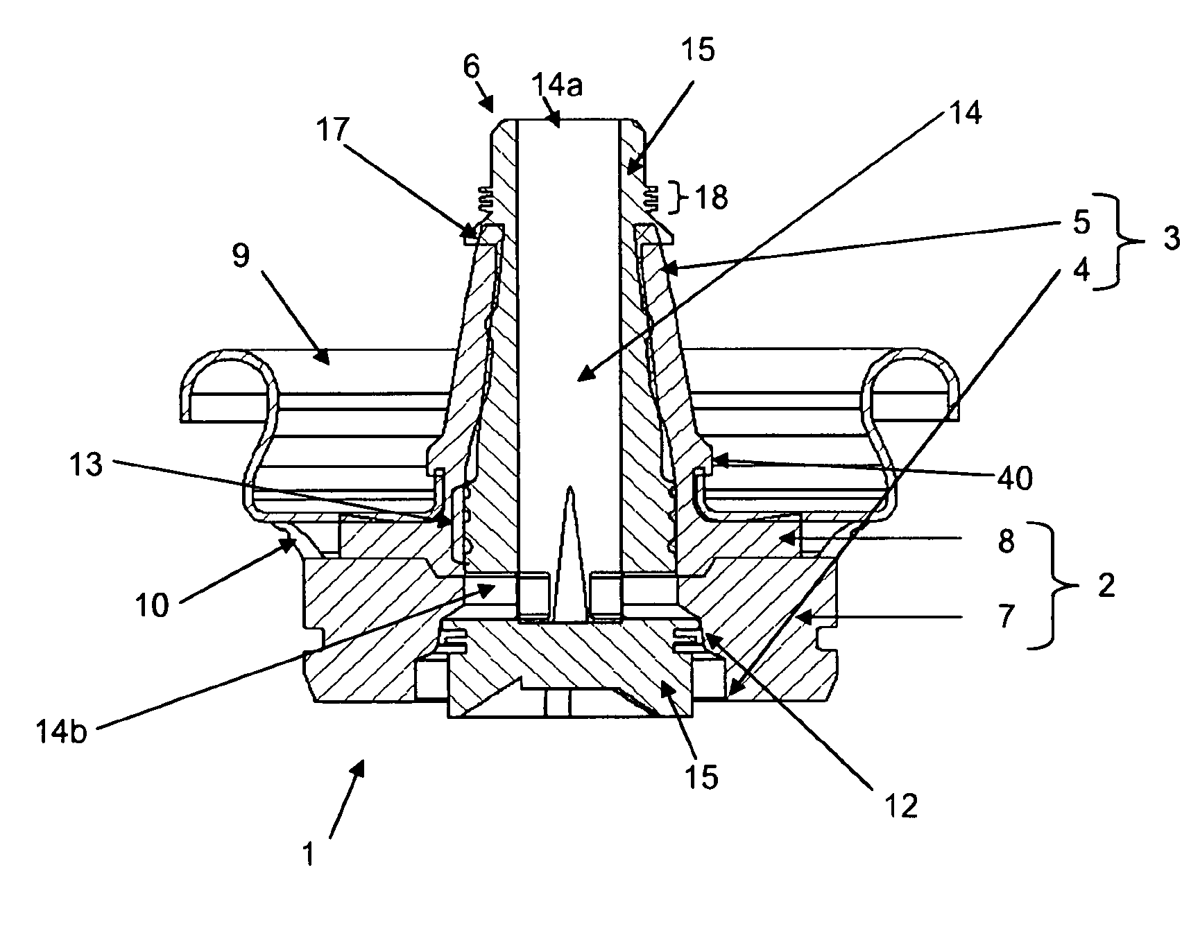
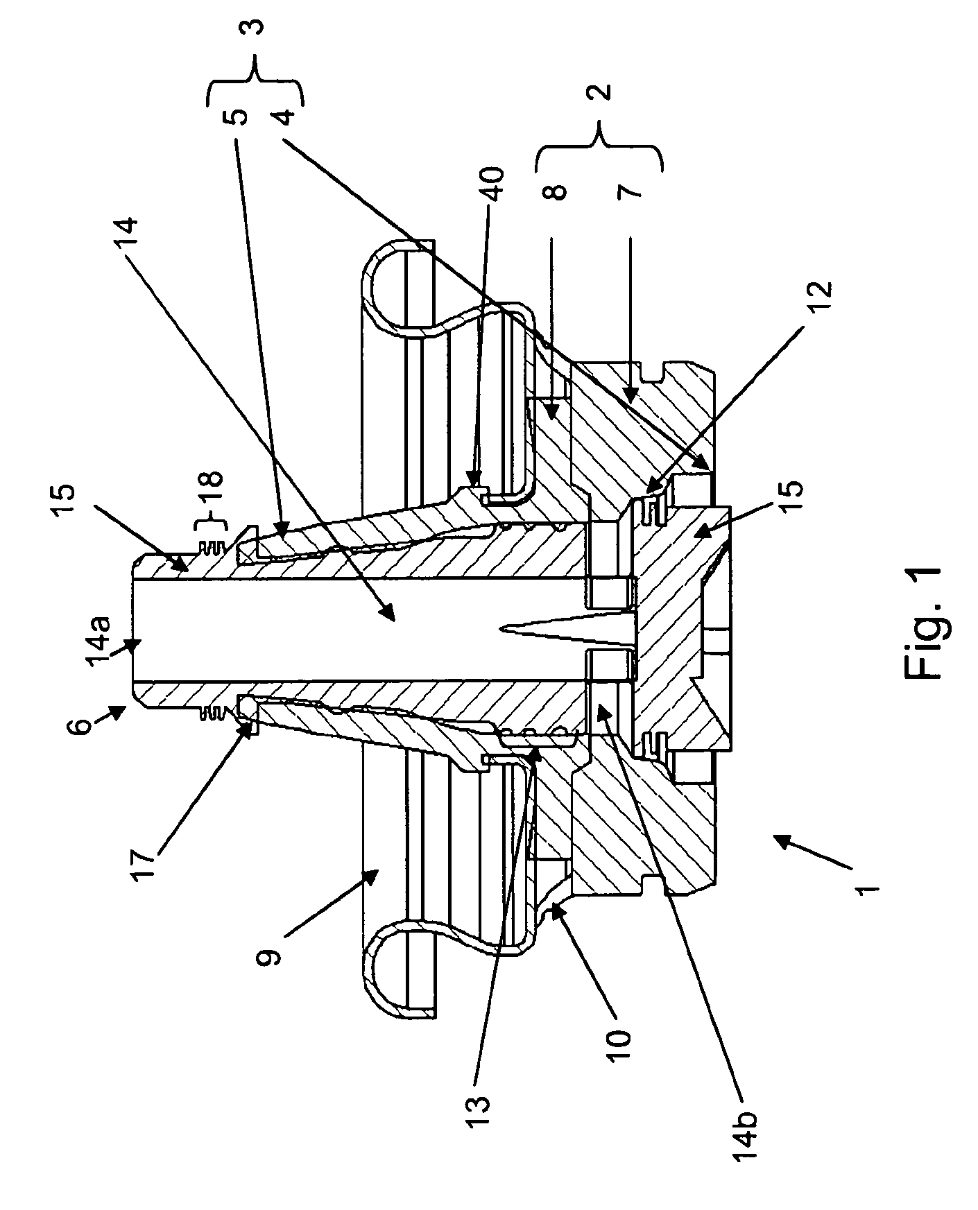
[0017]The present invention relates to a valve for a container, the valve comprising:[0018]a grommet defining a channel with an inlet end and an outlet end;[0019]a stem, slideably arranged in said channel;

the grommet comprising a first part provided at said inlet end and a second part provided at said outlet end, characterized in that the first part has a hardness greater than the hardness of the second part.

[0020]An advantage of a valve according to the present invention is that, when mounted in the cup of a container, the first (hard) part is located inside the container and prevents the valve from detaching from the cup when overpressure occurs inside the container.

[0021]Another advantage of the present invention is that the valve can be assembled separately from the container, as no overmoulding is required to fasten the valve to the container's cup, thereby simplifying production and reducing production cost.

[0022]Said first part of the container is preferably manufactured from...


PUM

PropertyMeasurementUnit
Young's modulusaaaaaaaaaa
hardnessaaaaaaaaaa

Abstract

The present invention is a valve for a container. The valve includes a grommet defining a channel with an inlet end and an outlet end. The valve has a stem, slideably arranged in the channel, and the grommet includes a first part provided at the inlet end and a second part provided at the outlet end. The first part has a hardness greater than the hardness of the second part.

Description

FIELD OF THE INVENTION[0001]The present invention relates to a new aerosol valve for a pressurized fluid container, more particularly for one component polyurethane foam applications.BACKGROUND OF THE INVENTION[0002]It is known generally known to store fluids under pressure in containers (cans or vessels) in a wide field of applications. The fluids are usually dispensed from the container by means of a valve arranged in a cup of the container.[0003]A well-known application is sprayable foams used in both industrial applications and by hobbyists. As such, containers with sprayable foam can be exposed to rather extreme conditions in terms of temperature and pressure.[0004]Under these extreme conditions, the pressure in the container may rise and the valve may detach from the container creating potential safety issues.[0005]In order to prevent the above, several safety measures are used, such as providing an overpressure relief valve or providing “burst parts” in the container. However...

Claims


Application Information

Patent Timeline
Patent Type & Authority Patents(United States)
IPC IPC(8): B65D83/34B65D83/14B65D83/46B65D83/00B65D83/28B65D83/20B65D83/48
CPCB65D83/46B65D83/201B65D83/345B65D83/28B65D83/756B65D83/753B65D83/48Y10T16/05B65D83/38
Inventor DE, SCHRIJVER, ASTER
Owner ALTACHEM
Why Eureka
Try Eureka