
Storage medium storing load detecting program and load detecting apparatus

a technology for storing a storage medium which is applied in the field of storage medium storing a load detecting program and a load detecting apparatus, can solve the problems of time lag between, inability to accurately determine difficulty in accurately determining the motion of the subject, etc., to achieve accurate determination whether or not the motion is occurring.

Active Publication Date: 2014-12-09
NINTENDO CO LTD
View PDF421 Cites 4 Cited by
  • Summary
  • Abstract
  • Description
  • Claims
  • Application Information

AI Technical Summary

Benefits of technology

The present invention is for a program and device that can accurately detect when a player puts their foot on or down from a platform. This is done by counting the time from when the player performs the motion. This technology helps to determine the timing of the player's motion and ensures that it can be accurately judged.

Problems solved by technology

However, in the above-described Patent Documents 1 and 2, although changes of the load in a state that the foot of the subject is put on the detection plate provided with the load detecting means (the balance between right and left and shift of the center of gravity) can be measured, there is a problem in that it is difficult to accurately determine a motion of putting the foot on and down from the detection plate like a step-up-and-down exercise.
However, at this step, since the subject merely puts the foot off from the detection plate, and has not finished the motion of putting the foot on the ground, if the motion is determined here, a time lag occurs between the timing when the motion is actually performed and the timing when the determination of the motion is performed in the apparatus.
Thus, this makes it impossible to accurately determine the motion of the subject, and this gives the subject a strong uncomfortable feeling and an unnatural impression.
Since the above-described Patent Documents 1 and 2 only disclose the measurement of the changes of the load with both of the feet are put on the plate, it is impossible to detect timing when the foot is put on the ground, so that such problems cannot be solved.

Method used


Image

  • Storage medium storing load detecting program and load detecting apparatus
  • Storage medium storing load detecting program and load detecting apparatus
  • Storage medium storing load detecting program and load detecting apparatus

Examples


Embodiment Construction

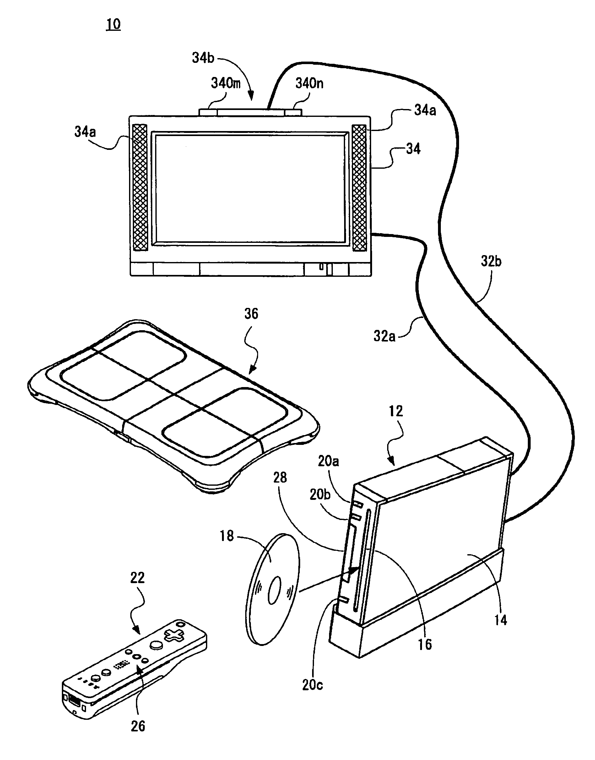
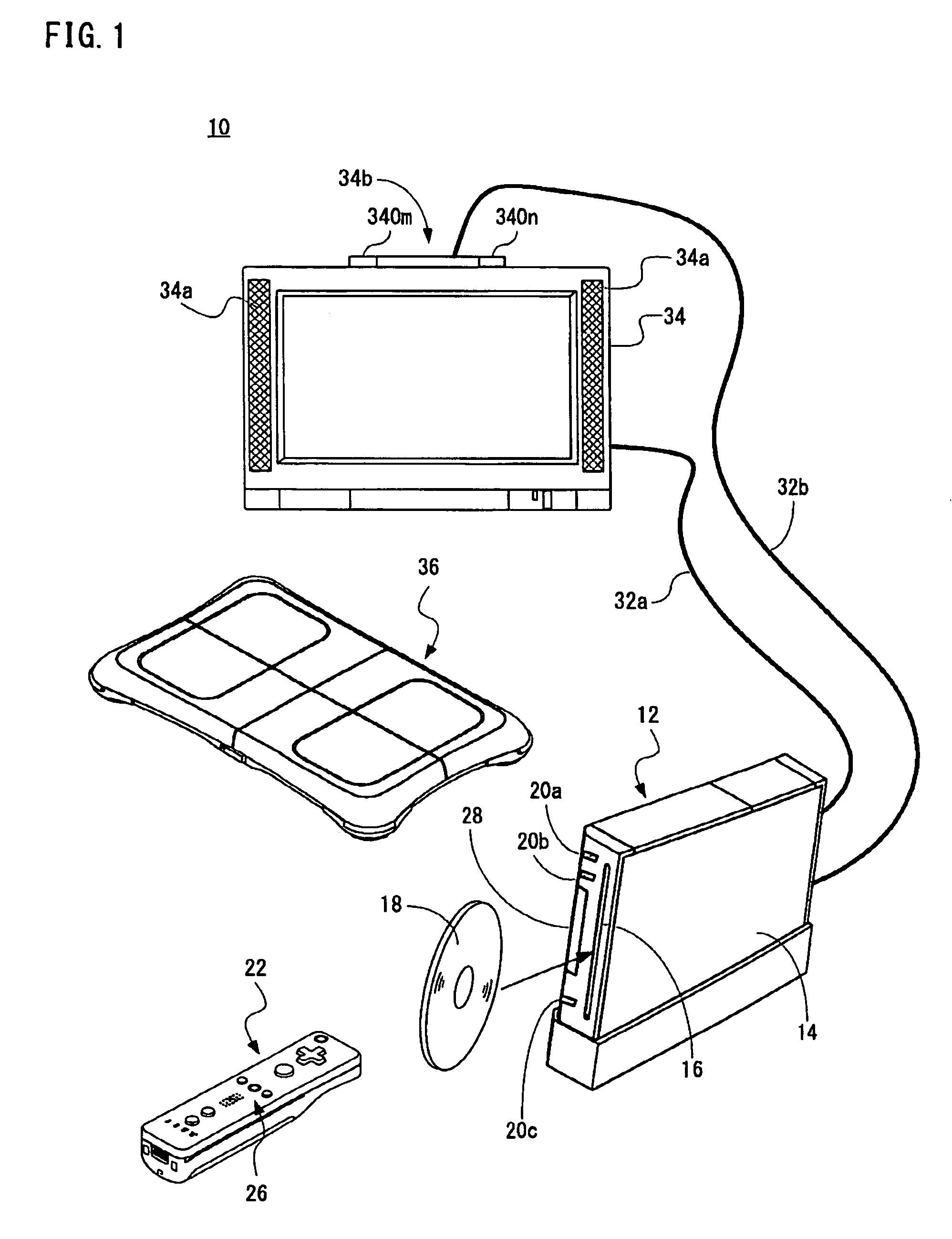
[0050]Referring to FIG. 1, a game system 10 of one embodiment of the present invention includes a video game apparatus hereinafter, simply referred to as “game apparatus”) 12, a controller 22 and a load controller 36. In this embodiment, the game apparatus 12 and the load controller 36 function as a load detecting apparatus. Although illustration is omitted, the game apparatus 12 of this embodiment is designed such that it can be connected to four controllers (22, 36) at the maximum. Furthermore, the game apparatus 12 and the respective controllers (22, 36) are connected by radio. The wireless communication is executed according to a Bluetooth (registered trademark) standard, for example, but may be executed by other standards such as infrared rays, a wireless LAN.

[0051]The game apparatus 12 includes a roughly rectangular parallelepiped housing 14, and the housing 14 is furnished with a disk slot 16 on a front surface. An optical disk 18 as one example of an information storage medi...


PUM


Abstract

A load detecting apparatus includes a load controller, and judges a motion of a player on the basis of detected load values. Judgment timing for a motion of putting the feet on and down from the controller is decided on the basis of an elapsed time from an instruction of a motion. In a case that a step-up-and-down exercise is performed, a judgment timing of a motion for bringing about a state both of the feet are put down on a ground at a fourth step is decided on the basis of a judgment timing of a motion of putting a third step down.

Description

CROSS REFERENCE OF RELATED APPLICATION[0001]The disclosure of Japanese Patent Application No. 2007-261798 is incorporated herein by reference.BACKGROUND OF THE INVENTION[0002]1. Field of the Invention[0003]The invention relates to a storage medium storing a load detecting program and a load detecting apparatus. More specifically, the present invention relates to a storage medium storing a load detecting program and a load detecting apparatus which perform processing by detecting load values imposed on a support plate on which a foot of a player is put.[0004]2. Description of the Related Art[0005]Conventionally, a load detecting apparatus equipped with a sensor for detecting a load of a subject is known in a field of medical equipment for purpose of exercises such as rehabilitation.[0006]For example, in a Patent Document 1 (Japanese Patent Application Laid-Open No. 62-34016 [G01G 19 / 00, A61B 5 / 10, A61H 1 / 00, G01G 23 / 37]), a variable load display apparatus provided with two load senso...

Claims


Application Information

Patent Timeline
Patent Type & Authority Patents(United States)
IPC IPC(8): A63F9/24A63F13/40A63F13/20
CPCA63F2300/1043A63F2300/638A63F13/06A63F2300/1068A63F13/10A63F2300/6045A63F2300/69A63F2300/305A63F13/65A63F13/5375A63F13/42A63F13/24A63F13/214A63F13/525A63F2300/6661A63F13/44A63F13/45A63F13/218
Inventor OKAMOTO, MOTOIKASAMATSU, SHIGEHIRO
Owner NINTENDO CO LTD
Learn More