
Method for manufacturing lithium secondary battery

a secondary battery and lithium-ion battery technology, which is applied in the direction of cell components, final product manufacturing, sustainable manufacturing/processing, etc., can solve the problems of unfavorable uniform dispersibility in solvent, unfavorable temperature and/or drying time of positive electrode mixture layer-forming slurry, and particle disintegration, etc., to achieve excellent coating properties, excellent conductivity, and excellent coating properties of positive electrode current collectors

Active Publication Date: 2014-12-09
TOYOTA JIDOSHA KK
View PDF8 Cites 0 Cited by
  • Summary
  • Abstract
  • Description
  • Claims
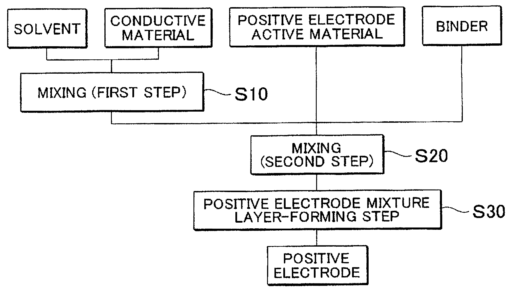
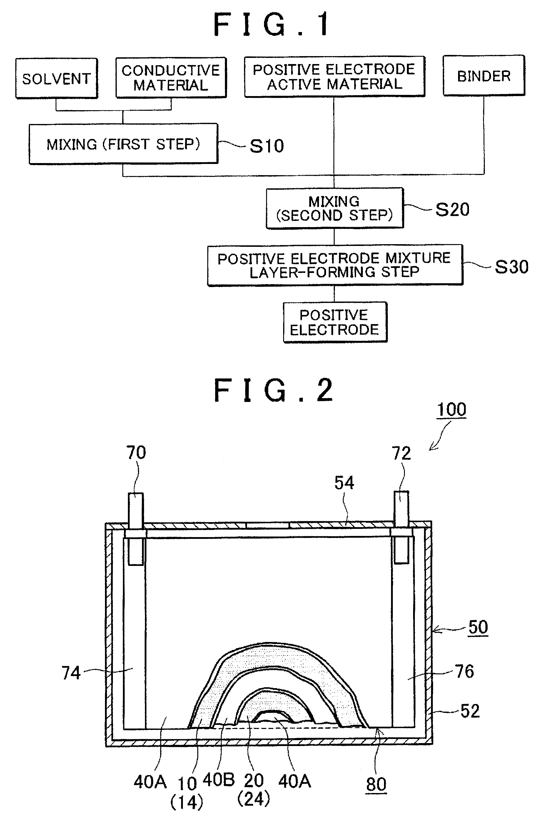
  • Application Information

AI Technical Summary

Benefits of technology

[0009]The present invention provides a method for manufacturing a lithium secondary battery, in which when the dispersibility of a conductive material in a positive electrode mixture layer-forming slurry is improved, the battery performance is improved (low IV resistance is realized, for example).
[0010]The present invention relates to a method for manufacturing a lithium secondary battery. The method for manufacturing includes: preparing a first slurry by a dispersing treatment where a conductive material containing conductive carbon fine particles in a solvent; preparing a second slurry by mixing the first slurry with a positive electrode active material and a binder; imparting the second slurry on a positive electrode current collector to form a positive electrode mixture layer; and forming a lithium ion secondary battery provided with the current collector on which the positive electrode mixture layer is formed. Here, the dispersing treatment is conducted in such a manner that a ratio (D90 / D10) of a particle size at 90% accumulation (D90) of the conductive material to a particle size at 10% accumulation (D10) of the conductive material. The particle size at 90% accumulation (D90) of the conductive material and the particle size at 10% accumulation (D10) of the conductive material are based on a particle size distribution measurement, may be 10 or more and 200 or less. Like this, firstly, only the conductive material is dispersed in a solvent to crush agglutinated conductive material. Thereby, the conductive material can be excellently dispersed in the solvent. Further, a conductive material that satisfies the particle size range has a relatively broad distribution of particle size; accordingly, the conductive material can preferably fill voids between particles of a positive electrode active material (for example, large voids are filled with coarse particles and fine voids are filled with fine particles). Accordingly, a conductive path in the positive electrode mixture layer (that is, contact area between a positive electrode active material and a conductive material) becomes excellent, and in a lithium secondary battery provided with the positive electrode mixture layer like this, the battery performance can be improved (low IV resistance is realized, for example).
[0011]The particle size at 90% accumulation (D90) based on the particle size distribution measurement may be one half or more and twice or less a particle size at 50% accumulation (D50) of the positive electrode active material, which is based on the particle size distribution measurement. When the dispersing treatment is performed so as to satisfy a particle size like this, voids between particles of the positive electrode active material can be preferably filled. Accordingly, in a positive electrode mixture layer, a stronger conductive path can be formed, and in a lithium secondary battery provided with the positive electrode mixture layer like this can improve the battery performance (low IV resistance is realized, for example).

Problems solved by technology

However, since the conductive carbon fine particles have a small primary particle size such as several tens nanometers and are strong in cohesion force, it is difficult to uniformly disperse in a solvent.
However, when an amount of solvent is increased like this, a temperature and / or a time for drying the positive electrode mixture layer-forming slurry become unfavorably high and / or long.
Further, there was a concern that due to a strong shearing action between media, particles are disintegrated to increase the viscosity of a dispersing system or to cause excess dispersion (re-agglomeration of once-dispersed particles) thereof.
An increase in the viscosity and the localization of a particle size distribution of the conductive material like this not only deteriorate the work efficiency but also unfavorably induce deterioration of battery performance (an increase in IV resistance, for example).

Method used


Image

  • Method for manufacturing lithium secondary battery
  • Method for manufacturing lithium secondary battery
  • Method for manufacturing lithium secondary battery

Examples


example 1

[0068]In a high shear homogenizer (Type “MT-V45”, manufactured by KINEMATICS), 2.3 kg of N-methyl-2-pyrrolidone (NMP) as a solvent was put, in the solvent 215 g of acetylene black (AB; trade name: DENKA BLACK POWDER, manufactured by DENKI KAGAKU KOGYO KK) was added as a conductive material, and a mixture was stirred for 15 min at the shearing speed of 30000 s−3 to disperse the AB in the solvent (first step). Here, a particle size distribution of the conductive carbon fine particles contained in the solvent was measured by a laser diffraction particle size analyzer (type: “MT3000”, manufactured by MicroTrack Co., Ltd.). Obtained results are shown in corresponding places of Table 1. In the Table, D10, D90 and D90 / D10, respectively denote a particle size at 10% accumulation, a particle size at 90% accumulation, and a ratio (D90 / D10) of the particle size at 90% accumulation (D90) and the particle size at 10% accumulation (D10).

[0069]A LiNi1 / 3Co1 / 3Mn1 / 3O2 powder (NCM; a particle size at ...

example 2 to example 9

[0070]Except that, in the first step, a total stirring time was set to 15 min that is the same as that in example 1 and a timing for charging the AB (that is, a time until the AB is added from the start of stirring) was changed, in a manner similar to that of example 1, positive electrode mixture layer-forming slurries were prepared. The smaller the number of examples is, the faster the timing for charging the AB is, that is, the longer the stirring time after the AB was added is. Also in each of Examples 2 to 9, in a manner similar to that of example 1, a particle size distribution in the first step and the viscosity and a particle size in the second step were measured. Obtained results are illustrated in corresponding places of Table 1.

example 10

[0071]Except that, in the first step, with a bead mill (type name: “LABSTAR LMZ06”, manufactured by Ashizawa FineTech Ltd.) and with beads of φ0.5 mm as a crushing media, the mixture was stirred for 15 min to disperse AB in a solvent, in a manner similar to that of example 1, a positive electrode mixture layer-forming slurry was prepared. Also of Example 10, in a manner similar to that of example 1, a particle size distribution in the first step and the viscosity and a particle size in the second step were measured. Obtained results are illustrated in corresponding places of Table 1.


PUM

PropertyMeasurementUnit
particle sizeaaaaaaaaaa

Abstract

A method for manufacturing a lithium secondary battery includes a first step of dispersing a conductive material in a solvent to prepare a conductive slurry; and a second step of mixing the prepared conductive slurry, a positive electrode active material and a binder to prepare a positive electrode mixture layer-forming slurry; wherein the first step is conducted so that a ratio of a particle size at 10% accumulation to a particle size at 90% accumulation, which are based on a particle size distribution measurement of the conductive material, is 10 or more and 200 or less.

Description

INCORPORATION BY REFERENCE[0001]The disclosure of Japanese Patent Application No. 2011-222311 filed on Oct. 6, 2011 including the specification, drawings and abstract is incorporated herein by reference in its entirety.BACKGROUND OF THE INVENTION[0002]1. Field of the Invention[0003]The present invention relates to a method for manufacturing a lithium secondary battery (typically a lithium ion battery). In more detail, the present invention relates to a method for manufacturing a positive electrode of the battery.[0004]2. Description of Related Art[0005]A lithium secondary battery including a lithium ion battery is smaller in size, lighter in weight and higher in the energy density than a conventional battery. From these features, the lithium secondary battery is widely used in a commercial field (a power source for personal computers and portable terminals). Further, from the viewpoint of high output density, the lithium secondary battery can be used also as a high-output power sour...

Claims


Application Information

Patent Timeline
Patent Type & Authority Patents(United States)
IPC IPC(8): H01M4/583B60K1/00B05D5/12H01M4/64H01M4/04
CPCH01M4/583H01M4/64Y02E60/122H01M4/04Y02T10/7011H01M4/0404H01M4/625Y10T29/49115H01M4/139Y02E60/10Y02P70/50Y02T10/70
Inventor UEZONO, TOMOYUKI
Owner TOYOTA JIDOSHA KK
Learn More