
Dynamic modular control system

a modular control system and dynamic technology, applied in diagnostics, medical science, healthcare informatics, etc., can solve the problems of complex control room design, inability to perform all control functions, and inability of centralized computer to control the functions of one or more local control devices

Active Publication Date: 2014-12-09
GENERAL ELECTRIC CO
View PDF11 Cites 6 Cited by
  • Summary
  • Abstract
  • Description
  • Claims
  • Application Information

AI Technical Summary

Benefits of technology

The modular control system provides robust and redundant control and monitoring capabilities, allowing for real-time operation and management of medical systems, even if individual devices become inoperative, by automatically reconfiguring and redistributing control functions across the network.

Problems solved by technology

The complexity of control room designs may vary from a simple layout of two plugged monitors to a highly complex set of multiple integrated systems.
While the centralized computer is configured to perform control functions on the system, the centralized computer typically does not perform all the control functions.
For example, the centralized computer may not be able to control the functions of one or more of the local control devices.
Accordingly, the centralized computer located in the control room does not provide a redundancy to operate the system in the event that the local control device becomes inoperative.

Method used


Image

  • Dynamic modular control system
  • Dynamic modular control system
  • Dynamic modular control system

Examples


Embodiment Construction

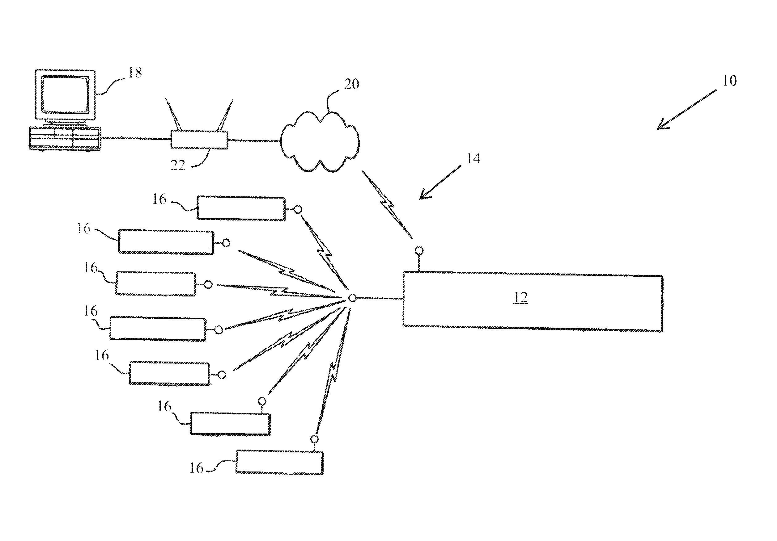
[0013]The foregoing summary, as well as the following detailed description of certain embodiments, will be better understood when read in conjunction with the appended drawings. To the extent that the figures illustrate diagrams of the functional blocks of various embodiments, the functional blocks are not necessarily indicative of the division between hardware circuitry. Thus, for example, one or more of the functional blocks (e.g., processors, controllers, circuits or memories) may be implemented in a single piece of hardware or multiple pieces of hardware. It should be understood that the various embodiments are not limited to the arrangements and instrumentality shown in the drawings.

[0014]As used herein, an element or step recited in the singular and proceeded with the word “a” or “an” should be understood as not excluding plural of said elements or steps, unless such exclusion is explicitly stated. Furthermore, references to “one embodiment” are not intended to be interpreted ...


PUM


Abstract

A modular control system including a plurality of individual touch screen devices, each touch screen device including a display unit, a touch input, a computing device, a network connection, and a programming logic for controlling a remote system and displaying a status of the remote system on the touch screen device, the remote system having network connectivity to enable the remote system to exchange information with and respond to instructions from the touch screen devices, the touch screen devices configured for automatic self-synchronization based on a status of the remote system or a status of at least one of the touch screen devices.

Description

BACKGROUND OF THE INVENTION[0001]The subject matter disclosed herein relates generally to control systems, and more particularly to a dynamic modular control system for controlling an imaging system.[0002]Control room design plays a major role in acquiring, processing, managing and efficiently presenting data, as well as controlling industrial and other devices. Control rooms are used in various applications such as healthcare applications, military applications, emergency services, the security industry, as well as the utilities, transportation, satellite systems, nuclear power plants, to name just a few applications.[0003]The design and layout of control rooms has changed over the years to achieve a broader spectrum of functionality and efficiency. The complexity of control room designs may vary from a simple layout of two plugged monitors to a highly complex set of multiple integrated systems. In operation, the control room is utilized to monitor and control the operation of a re...

Claims


Application Information

Patent Timeline
Patent Type & Authority Patents(United States)
IPC IPC(8): G06F3/041
CPCA61B6/548G06F3/0488G16H30/20G16H40/67
Inventor BELLO, MUSODIQ O.AVINASH, GOPAL BILIGERIHOFORD, JOHN DAVIDNITTALA, APARNA
Owner GENERAL ELECTRIC CO
Learn More