Communication system, node device, communication method in the communication system, and program

a communication system and node technology, applied in the field of communication systems, can solve the problems that failure recovery cannot be performed at a high speed, and achieve the effect of high speed, accurate number of hops, and high speed

Inactive Publication Date: 2014-12-09
NEC CORP
View PDF9 Cites 159 Cited by
  • Summary
  • Abstract
  • Description
  • Claims
  • Application Information

AI Technical Summary

Benefits of technology

[0056]According to the present invention, by selecting an alternative route as far as a transmission terminal node that excludes a path from the transmission terminal node on a path along which transmission has been performed to a node that has detected a failure, the number of hops that are used after failure recovery can be reduced as much as possible, and failure recovery can be performed at a high speed and accurately.

Problems solved by technology

However, the conventional failure recovery is problematic in that the failure recovery can not be performed at a high speed because much time is required in switch settings and in confirming completion of the settings during the failure recovery operation.
On the other hand, if its own node is not a node on the standby path corresponding to the active path, the failure of which is detected, the node transmits the received failure notification signal through flooding without switching its switch.

Method used


Image

  • Communication system, node device, communication method in the communication system, and program
  • Communication system, node device, communication method in the communication system, and program
  • Communication system, node device, communication method in the communication system, and program

Examples


first exemplary embodiment

(First Exemplary Embodiment)

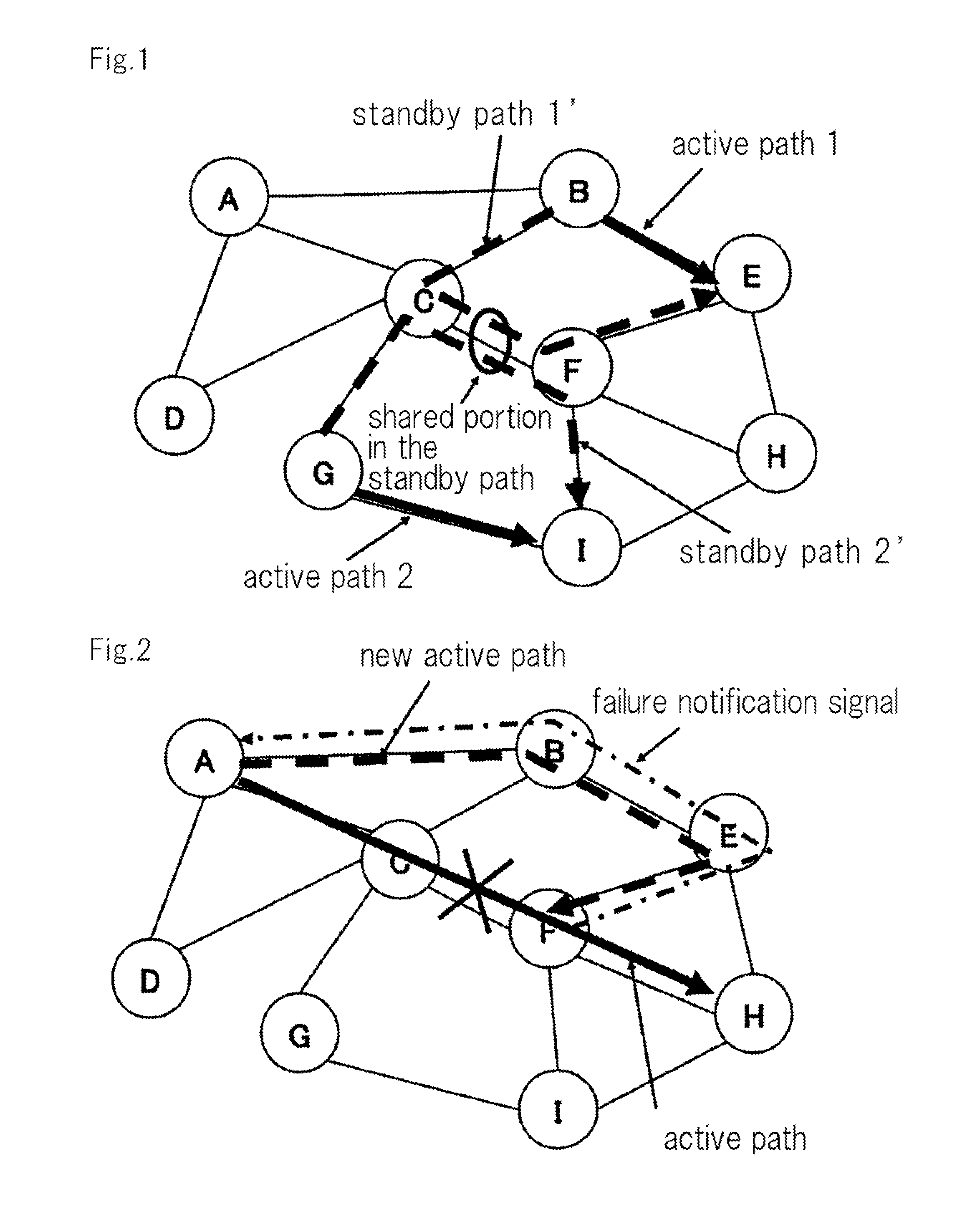
[0076]FIG. 2 is a view that illustrates an example of a network. There exist nodes A to I in this network, and a plurality of links are connected to each node.

[0077]Data transmission is usually performed on an active path indicated by a thick line in FIG. 1. However, when a failure, such as a link disconnection or a node failure, occurs on the active path, data transmission is performed via a new active path indicated by a dotted line in FIG. 1. In addition to data signals that are used for data transmission on the active path or new active path, there are control signals such as failure notification signals that are used for controlling each node. The signals are transmitted using different channels. Herein, the signals are transmitted using the same channel on the active path and the new active path. In this connection, FIG. 2 illustrates a case in which a failure occurred between nodes C and F.

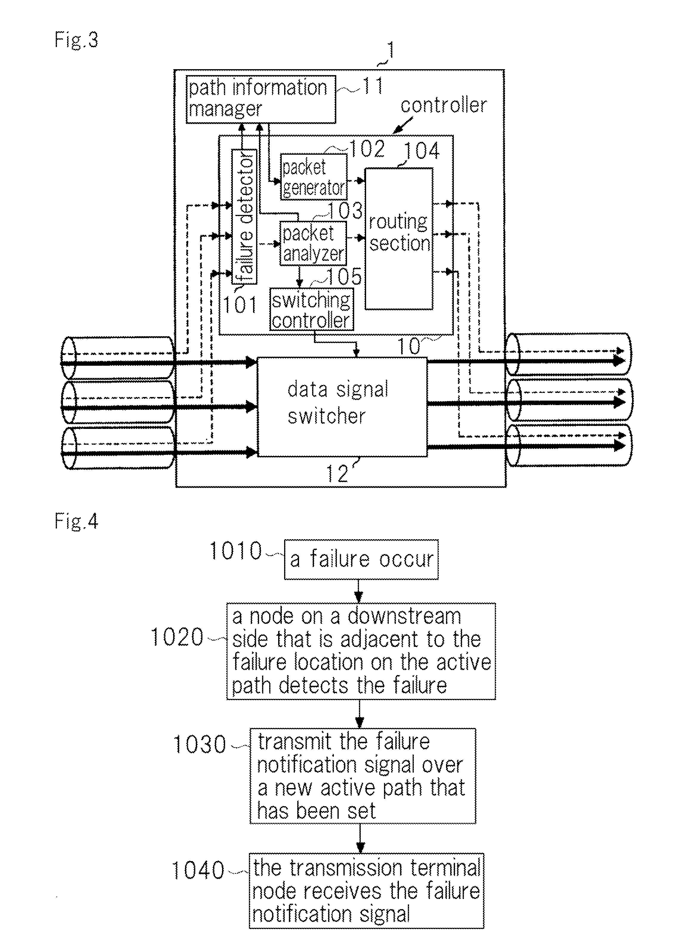
[0078]FIG. 3 is a block diagram that illustrates the config...

second exemplary embodiment

(Second Exemplary Embodiment)

[0098]Operations when a node on a new active path receives a failure notification signal will now be described in detail. Note that the configuration of the present exemplary embodiment is the same as that of the first exemplary embodiment.

[0099]FIG. 8 is a flowchart that illustrates an example of operations when a node on a new active path has received a failure notification signal.

[0100]When a node on a new active path receives a failure notification signal at step 2010, packet analyzer 103 analyzes the packet for the failure notification signal, and recognizes that the packet is for a failure notification signal at step 2020. At the same time, packet analyzer 103 recognizes the input port and output port in the packet. Next, at step 2030, packet analyzer 103 sets the input port and output port of data signal switcher 12 in the direction opposite to the transmission direction of the control packet through switching controller 105.

[0101]FIG. 9 illustrat...

third exemplary embodiment

(Third Exemplary Embodiment)

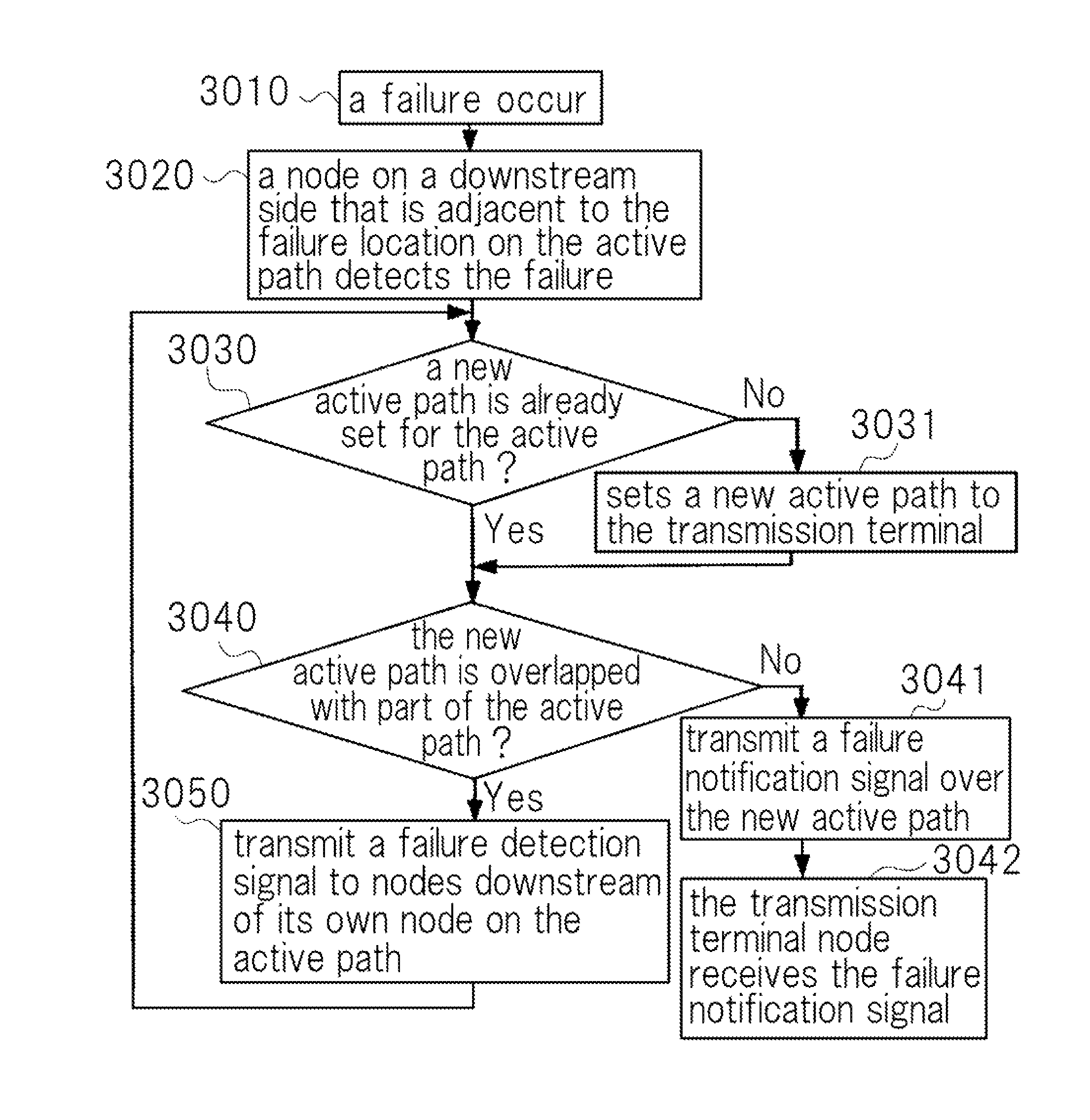
[0109]When setting a new active path from a node that detected a failure of a node adjacent thereto, there is a possibility that part of the new active path will overlap with the active path, as illustrated in FIG. 11. Therefore, according to the present exemplary embodiment, from the viewpoint of effective band utilization, setting of a new active path is performed such that paths do not overlap. Note that the configuration of the present exemplary embodiment is the same as that of the first exemplary embodiment.

[0110]FIG. 12 is a flowchart in the third exemplary embodiment that illustrates an example of operations in the network when a failure has occurred. The operations up to setting a new active path (step 3010 to step 3031) are the same as in the first exemplary embodiment.

[0111]After setting the new active path, the node that has detected the failure determines whether or not part of the new active path overlaps with the active path, at step 3040. ...


PUM


Abstract

A communication system comprises: failure detection means that detects a failure on a first transmission path over which data transmission is being performed; transmission path setting means that, when the failure exists in a link or a node that is located immediately before its own node, sets a second transmission path as far as a transmission terminal node, the second transmission path that excludes a path from the transmission terminal node to a node that has detected the failure within the first transmission path; first failure notification means that transmits a failure notification signal as far as the transmission terminal node over the second transmission path; new path switching means that, upon receipt of the failure notification signal, switches a switch for data transmission so that a path for new data transmission is the same path as a transmission path for the failure notification signal; and data transmission means that, upon the transmission terminal node receiving the failure notification signal, switches the switch to the second transmission path and performs a new data transmission over the second transmission path.

Description

TECHNICAL FIELD[0001]The present invention relates to a communication system, a node device, a communication method in the communication system, and a program which take into consideration a failure recovery of a network.BACKGROUND ART[0002]Failure recovery techniques are extremely important for communication networks such as a photonic network when considering how to ensure that a network will have high reliability. The term “failure recovery” refers to switching a path from a active path on which a failure has occurred to a standby path when a failure such as a link disconnection or a node failure occurs.[0003]A representative example of a failure recovery technique is 1:1 protection. Since the 1:1 protection technique does not cause data to flow on a standby path during normal operation, the 1:1 protection technique is receiving attention as a method that can make the maximum use of bands when considering the current situation in which increasing amounts of data are being transmi...

Claims


Application Information

Patent Timeline
Patent Type & Authority Patents(United States)
IPC IPC(8): H04L12/759H04L12/703H04L12/26H04L12/707H04L12/751H04L45/02H04L45/24H04L45/28
CPCH04L45/02H04L45/22H04L45/28H04L45/028
Inventor HAYASHITANI, MASAHIRO
Owner NEC CORP
Why Eureka
Try Eureka