Pre-chamber jet igniter and engine including combustion chamber employing the same

a jet igniter and combustion chamber technology, applied in the engine field, can solve the problems of imposing an inherent limit on the above-described combustion scheme, small flame kernel size, short duration, etc., and achieve the effect of reducing the generation of nox and improving fuel consumption

Active Publication Date: 2014-12-16
HYUNDAI MOTOR CO LTD
View PDF15 Cites 18 Cited by
  • Summary
  • Abstract
  • Description
  • Claims
  • Application Information

AI Technical Summary

Benefits of technology

[0013]Various aspects of the present invention provide for engine including a combustion chamber employing a pre-chamber jet igniter that combusts an air-fuel mixture, which is external air and an injected fuel mixed outside of the combustion chamber, and supplies a jet combustion flame of a large flame kernel created by the combustion into the combustion chamber, so that the fuel is ignited and exploded by the jet combustion flame (flame propagation), and the combustion of the combustion chamber is maintained reliable, thereby remarkably improving fuel consumption and reducing the generation of NOx using rapid cold combustion.
[0014]Various aspects of the present invention provide for engine including a combustion chamber employing a pre-chamber jet igniter that injects a jet combustion flame in the form of a large flame kernel supplied from outside the combustion chamber into the combustion chamber, so that the jet combustion flame serves as a source of ignition of the fuel injected into the combustion chamber, thereby eliminating air-fuel mixture ports through which air and fuel are supplied, and thus preventing liquefaction of the air-fuel mixture due to variations in the flow and pressure of the air-fuel mixture.
[0035]After the external air and the fuel injected into the air are mixed to form the air-fuel mixture and the air-fuel mixture is then combusted outside the combustion chamber of the engine, a jet combustion flame in the form of a large flame kernel may be supplied to the combustion chamber. As a result, it is possible to eliminate air-fuel mixture ports through which air and fuel are supplied, and thus to prevent liquefaction of the air-fuel mixture due to variation in the flow and pressure of the air-fuel mixture.
[0036]In addition, after the jet combustion flame in the form of the large flame kernel has been created in advance by the air-fuel mixture, which is external air mixed with a small quantity of fuel outside the combustion chamber, since the jet combustion flame is supplied to the combustion chamber, the combustion in the combustion chamber can be maintained reliable, thereby remarkably improving fuel consumption and reducing the generation of NOx using rapid cold combustion.
[0037]Further, since the jet combustion flame is first generated by the air-fuel mixture, which is external air mixed with a small quantity of fuel outside the combustion chamber, and is then supplied to the combustion chamber, it is possible to precisely control combustion (control the air-fuel ratio), and to secure the performance and reliability of the flame ignition in the combustion chamber.
[0038]Furthermore, since the shape of the jet combustion flame supplied to the space inside the combustion chamber is first determined accurately from outside the combustion chamber, it is possible to precisely calculate the quantity of fuel that is directly injected into the space inside the combustion chamber, thereby decreasing fuel consumption.

Problems solved by technology

However, if the spark plug generates the ignition sparks in the combustion chamber and the combustion flame kernel is created by the ignition flame in the combustion chamber, the size of the flame kernel is small, and its duration is short, which does not ensure complete combustion in the combustion chamber.
This problem imposes an inherent limit on the above-described combustion schemes.
In order to overcome this limit, lean burn (super lean burn) combustion can be applied to the engine, but the lean burn (super lean burn) combustion has another problem in that a large quantity of NOx is generated due to the high heat of combustion for improving fuel consumption.
In this instance, the generation of NOx can be decreased using DeNOx catalysts, but DeNOx catalysts are expensive, and thus increase costs, and decrease competitiveness.

Method used


Image

  • Pre-chamber jet igniter and engine including combustion chamber employing the same
  • Pre-chamber jet igniter and engine including combustion chamber employing the same
  • Pre-chamber jet igniter and engine including combustion chamber employing the same

Examples


Embodiment Construction

[0047]Reference will now be made in detail to various embodiments of the present invention(s), examples of which are illustrated in the accompanying drawings and described below. While the invention(s) will be described in conjunction with exemplary embodiments, it will be understood that present description is not intended to limit the invention(s) to those exemplary embodiments. On the contrary, the invention(s) is / are intended to cover not only the exemplary embodiments, but also various alternatives, modifications, equivalents and other embodiments, which may be included within the spirit and scope of the invention as defined by the appended claims.

[0048]Throughout the disclosure, like reference numerals refer to like parts throughout the various figures and embodiments of the present invention.

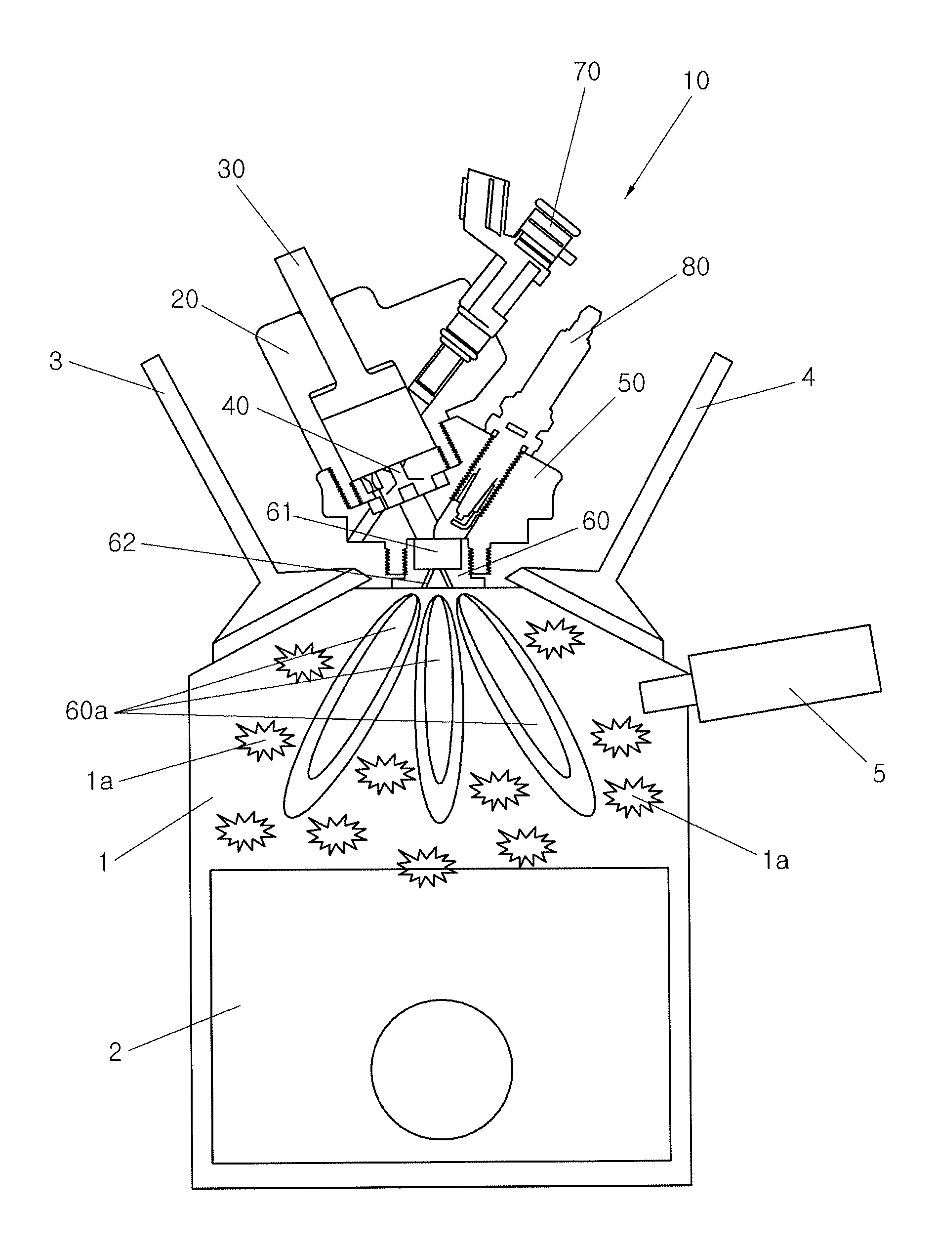
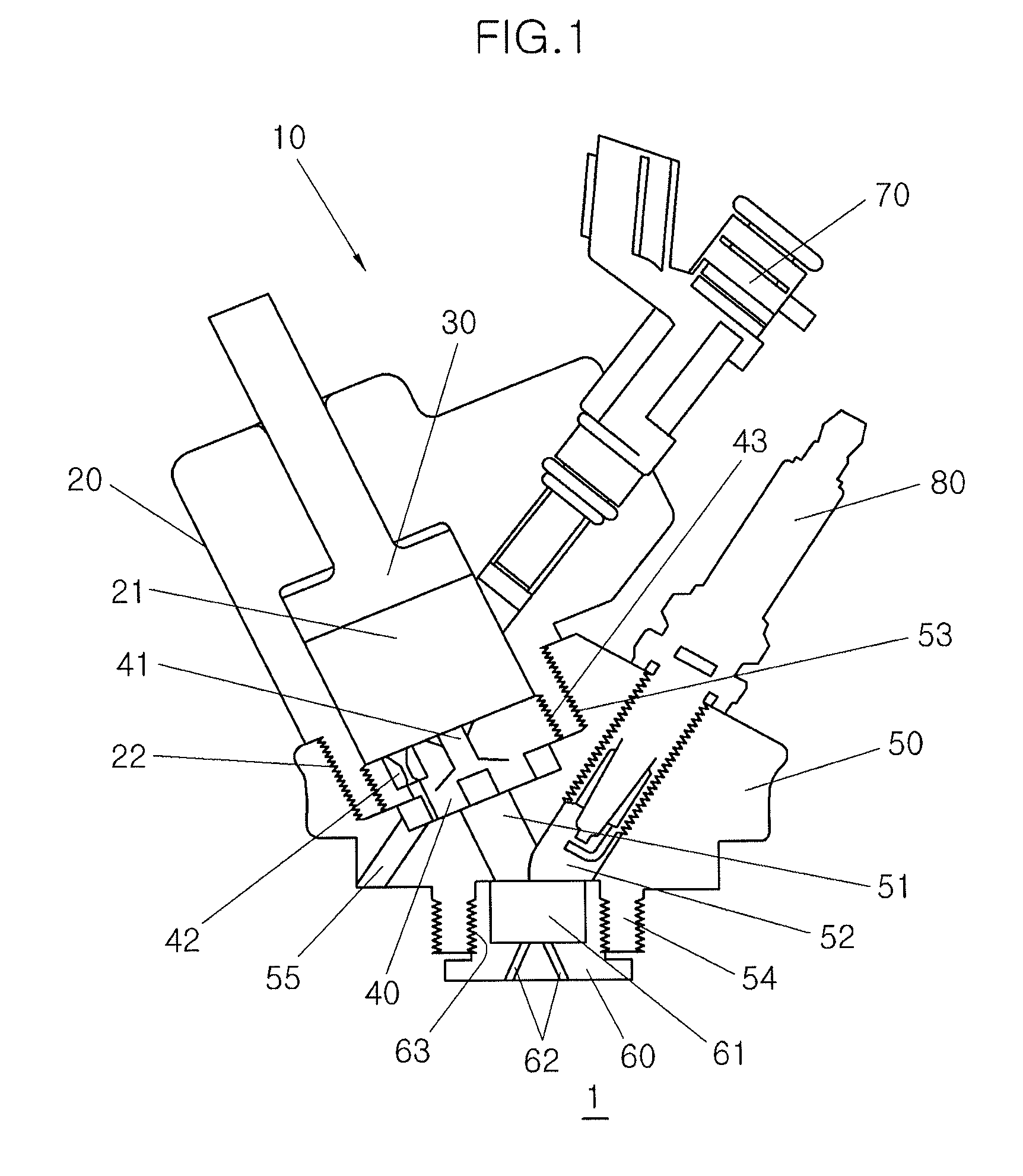
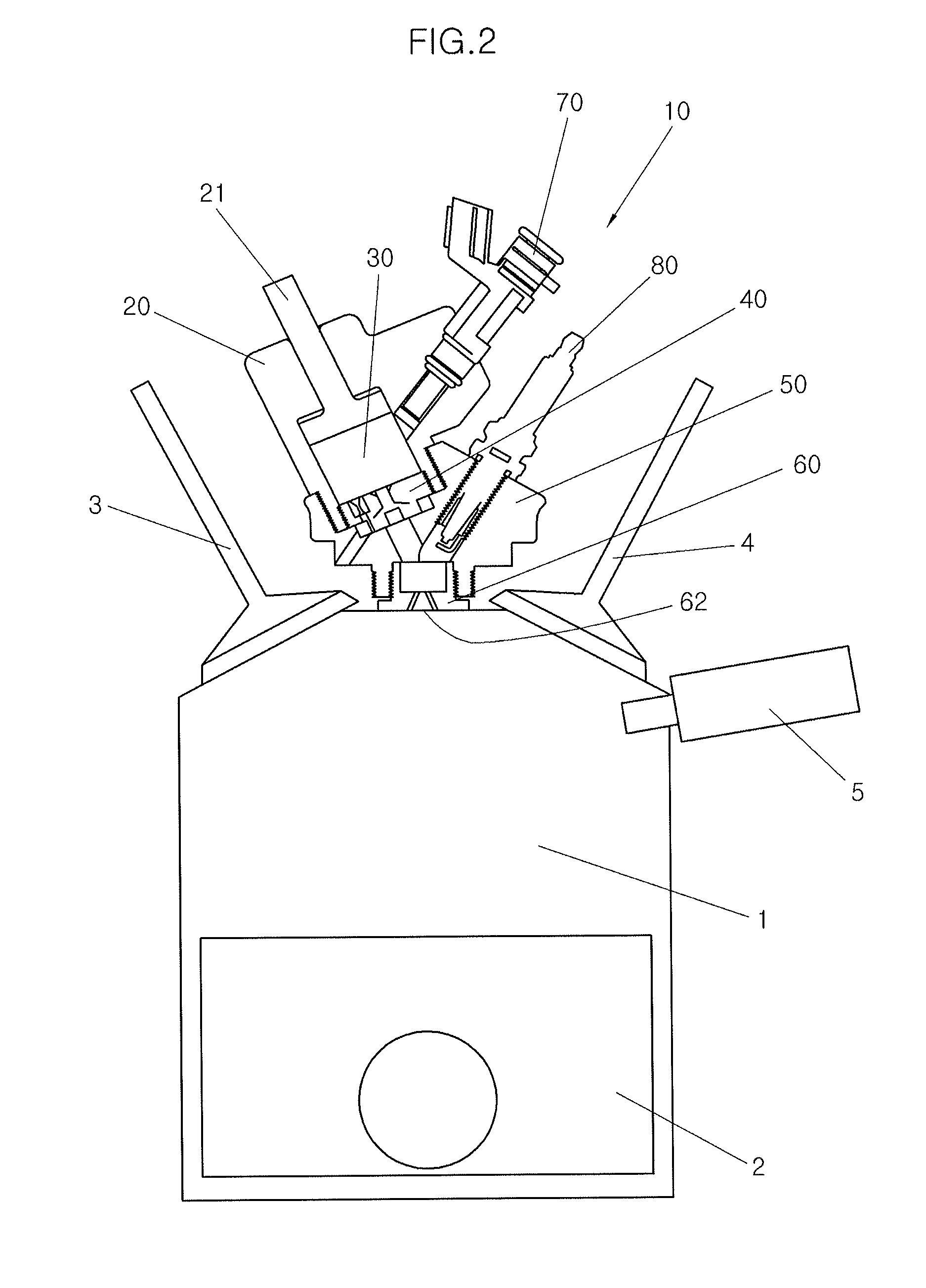
[0049]FIG. 1 illustrates the configuration of a pre-chamber jet igniter according to the present invention.

[0050]As shown in the figure, a pre-chamber jet igniter 10 includes a compressio...


PUM


Abstract

An engine includes a pre-chamber jet igniter which injects at least one jet combustion flame into the combustion chamber from the outside of the combustion chamber in which the piston reciprocates to generate power so that the injected jet combustion flame is utilized as the source of ignition of the fuel injected into the space in the combustion chamber to drive the explosion stroke such that combustion of the combustion chamber can be maintained reliable by the use of jet combustion flames in the form of large flame kernels, fuel consumption can be remarkably improved and the generation of NOx can be remarkably reduced using rapid cold combustion which is caused by the continuously reliable combustion, and, in particular, it is possible to prevent liquefaction of the air-fuel mixture due to variations in the flow and pressure of the air-fuel mixture flowing in the combustion chamber.

Description

CROSS-REFERENCE TO RELATED APPLICATIONS[0001]The present application claims priority of Korean Patent Application Number 10-2012-0021105 filed Feb. 29, 2012, the entire contents of which application is incorporated herein for all purposes by this reference.BACKGROUND OF INVENTION[0002]1. Field of Invention[0003]The present invention relates to an engine, particularly, to an engine including a combustion chamber employing a pre-chamber jet igniter that injects a jet combustion flame, which has been previously formed from an air-fuel mixture, into a space inside the combustion chamber, so that the jet combustion flame serves as a source of ignition of a fuel injected into the space inside the combustion chamber to ignite the fuel, thereby reliably maintaining combustion by use of the jet combustion flame as a large flame kernel and thus remarkably improving fuel consumption and reducing the generation of NOx.[0004]2. Description of Related Art[0005]In general engines, after fuel is di...

Claims


Application Information

Patent Timeline
Patent Type & Authority Patents(United States)
IPC IPC(8): F02B19/10F02B19/06F02B19/00
CPCF02B19/12F02B19/06F02B19/10F02B19/1085F02P15/006F02D41/3094Y02T10/125Y02T10/12F02P21/00F02P15/00
Inventor WOO, SOOHYUNGKWON, KIYOUNGKONG, JINKOOKKIM, YOUNGNAMKIM, JINSOON
Owner HYUNDAI MOTOR CO LTD
Why Eureka
Try Eureka