Method for operating a braking system

a technology of braking system and braking components, which is applied in the direction of braking system, braking components, transportation and packaging, etc., can solve the problem of rapid pressure buildup in the first chamber

Inactive Publication Date: 2014-12-16
CONTINENTAL TEVES AG & CO OHG
View PDF13 Cites 0 Cited by
  • Summary
  • Abstract
  • Description
  • Claims
  • Application Information

AI Technical Summary

Benefits of technology

[0008]The method proposed offers the advantage that a high-pressure accumulator of relatively small volume can be used for reasons of cost reduction and / or the small amount of installation space available without the need to accept significant sacrifices in terms of the rapidity of a pressure buildup in the braking system.
[0011]The high-pressure accumulator is preferably chargeable by the electrically controllable pressure provision device. To charge the high-pressure accumulator, it is advantageous if the shutoff valve provided between the electrically controllable pressure provision device and the high-pressure accumulator is opened and the pressure provision device is activated so as to produce pressure.

Problems solved by technology

This operation results in a rapid pressure buildup in the first chamber and hence in the brake master cylinder and the wheel brakes.

Method used


Image

  • Method for operating a braking system
  • Method for operating a braking system
  • Method for operating a braking system

Examples


Embodiment Construction

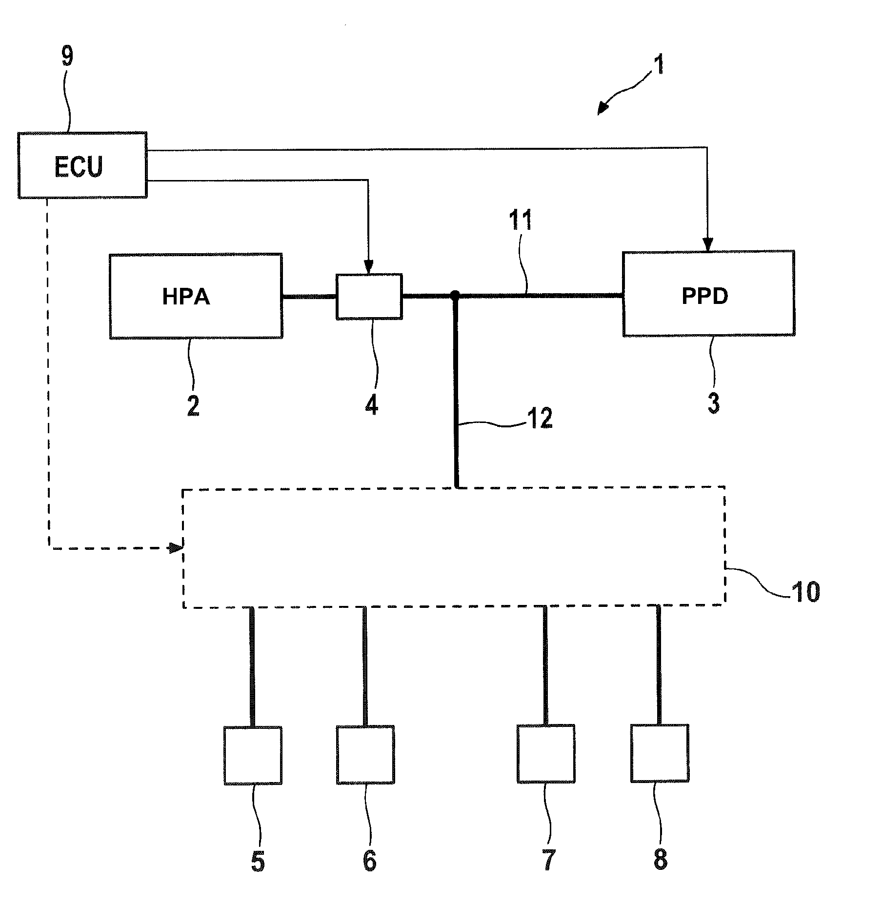
[0026]The illustrative embodiment of a braking system 1 for carrying out a method according to the invention, which is shown in a greatly simplified and schematic way in FIG. 1, comprises an electrically controllable pressure provision device 3, a high-pressure accumulator 2 (HDS) and an electrically controllable shutoff valve 4, by means of which a hydraulic connection 11 between the pressure provision device 3 and the high-pressure accumulator 2 can be established and interrupted. The shutoff valve 4 can be embodied as an electromagnetically actuable 2 / 2-way valve which is closed when deenergized, for example. The pressure provision device 3 and the high-pressure accumulator 2 are connected by a hydraulic connection 12 to wheel brakes 5, 6, 7, 8 of the braking system 1, thus allowing the wheel brakes 5, 6, 7, 8 to be supplied with pressure medium by means of the pressure provision device 3 and / or the high-pressure accumulator 2.

[0027]The wheel brakes 5, 6, 7, 8 can be supplied wit...


PUM


Abstract

A system and method for operating a hydraulic braking system) for motor vehicles with an electrically controllable pressure provision device), a high-pressure accumulator, which can be connected to the pressure provision device via a hydraulic connection), in which an electrically controllable shutoff valve is arranged, wheel brakes, which can be supplied with pressure medium by means of the pressure provision device and / or the high-pressure accumulator. An electronic control and regulating unit is provided for actuating the electrically controllable pressure provision device and / or the electrically controllable shutoff valve so as to regulate the hydraulic pressure which is provided by the pressure provision device and the high-pressure accumulator If a pressure buildup is carried out by activation of the pressure provision device, the high-pressure accumulator is connected only temporarily by at least partial opening of the shutoff valve.

Description

CROSS-REFERENCE TO RELATED APPLICATIONS[0001]This application claims priority to German Patent Application No. 10 2010 028 279.9, filed Apr. 28, 2010 and PCT / EP2010 / 070011, filed Dec. 17, 2010.FIELD OF THE INVENTION[0002]The invention relates to a method for operating a braking system for motor vehicles.BACKGROUND AND SUMMARY OF THE INVENTION[0003]German Patent DE 10 2009 033 499 A1 discloses a braking system having a brake master cylinder, which has at least one brake master cylinder piston and to which wheel brake circuits are connected, an electrically controllable pressure provision device, an electronic control and regulating unit for actuating the electrically controllable pressure provision device so as to regulate the hydraulic pressure output by the latter, and a pedal decoupling unit, which is inserted ahead of the brake master cylinder and has a retaining piston, the first annular surface of which combines with the brake master cylinder piston to delimit a first hydraulic...

Claims


Application Information

Patent Timeline
Patent Type & Authority Patents(United States)
IPC IPC(8): B60T7/04B60T13/66B60T8/40
CPCB60T2270/82B60T8/4077B60T7/042B60T8/4059B60T13/662
Inventor BILLER, HARALDBUSCHMANN, GUNTHER
Owner CONTINENTAL TEVES AG & CO OHG
Why Eureka
Try Eureka