Camera system and method for detecting the surroundings of a vehicle

a camera system and vehicle technology, applied in the field of camera system and vehicle surroundings detection, can solve problems such as inability to strik

Active Publication Date: 2014-12-16
ROBERT BOSCH GMBH
View PDF23 Cites 27 Cited by
  • Summary
  • Abstract
  • Description
  • Claims
  • Application Information

AI Technical Summary

Benefits of technology

[0006]The first partial area of the sensor surface allows the vehicle surroundings to be detected via the exposure by first optical radiation. Interference due to overlapping by second optical radiation may be avoided as a result of the time-offset exposure. The image data generated by exposing a second partial area with second optical radiation may thus be evaluated for determining the state of the window pane. The second partial area which is exposed by second optical radiation may also be at least partially exposed by first optical radiation. The time offset in the exposure of the first and second partial areas allows the second partial area to be irradiated with a sufficiently high intensity so that, despite overlapping by first optical radiation, for example, a reliable determination of the state of the window pane is possible.
[0016]In both variants for determining a state of the window pane, overlapping of first optical radiation, which is ascertained for detecting the vehicle surroundings, by second optical radiation is prevented, which otherwise could possibly interfere with detection of the vehicle surroundings. This allows second optical radiation to be generated with an intensity which makes it possible to determine the state of the window pane despite overlap with first optical radiation.

Problems solved by technology

The partial area of the image sensor which is irradiatable by the second optical radiation is concealed by a shutter in such a way that first optical radiation originating from the vehicle surroundings is blocked and is not able to strike this partial area.

Method used


Image

  • Camera system and method for detecting the surroundings of a vehicle
  • Camera system and method for detecting the surroundings of a vehicle
  • Camera system and method for detecting the surroundings of a vehicle

Examples


Embodiment Construction

[0026]Identical or corresponding components are denoted by the same or corresponding reference numerals in the figures.

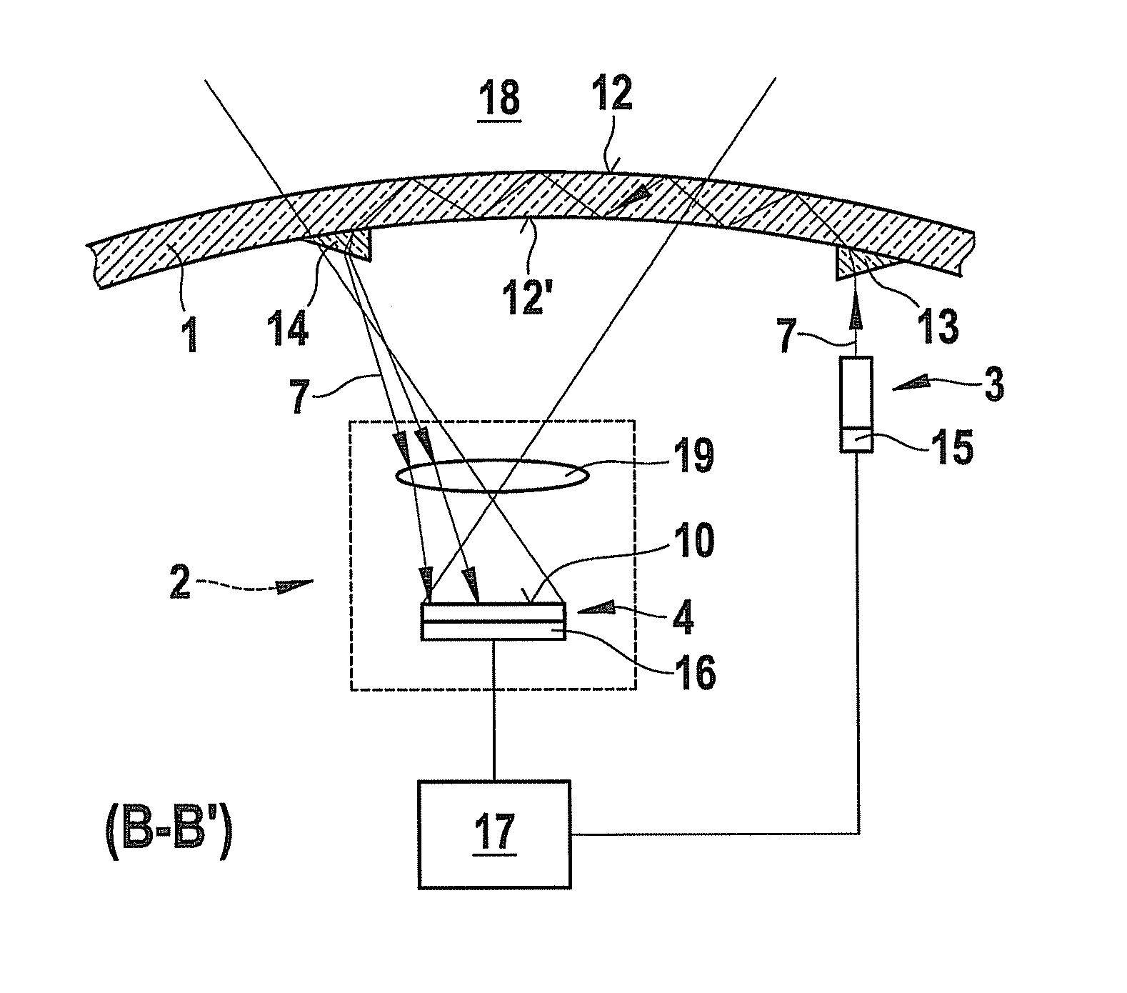
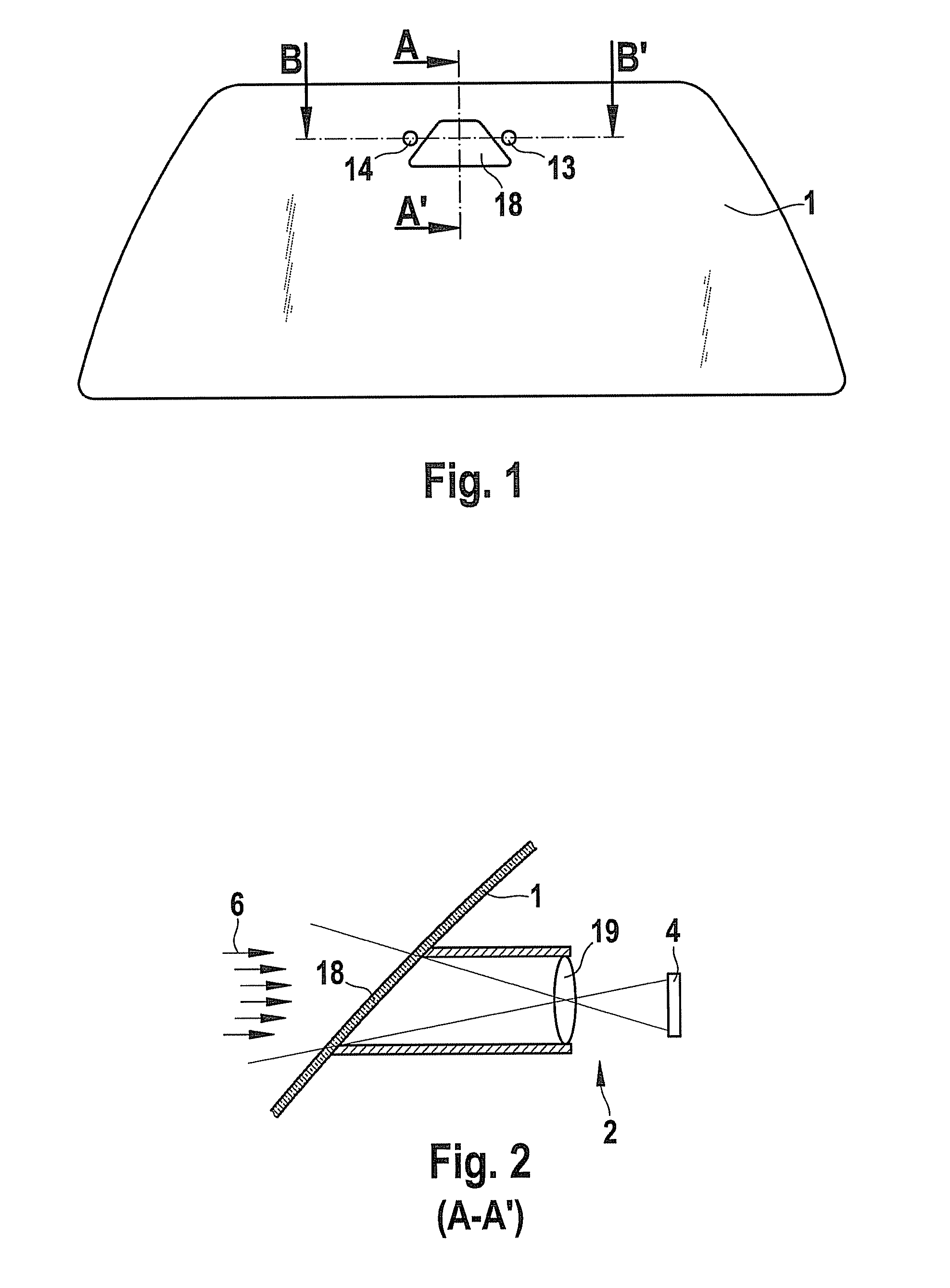
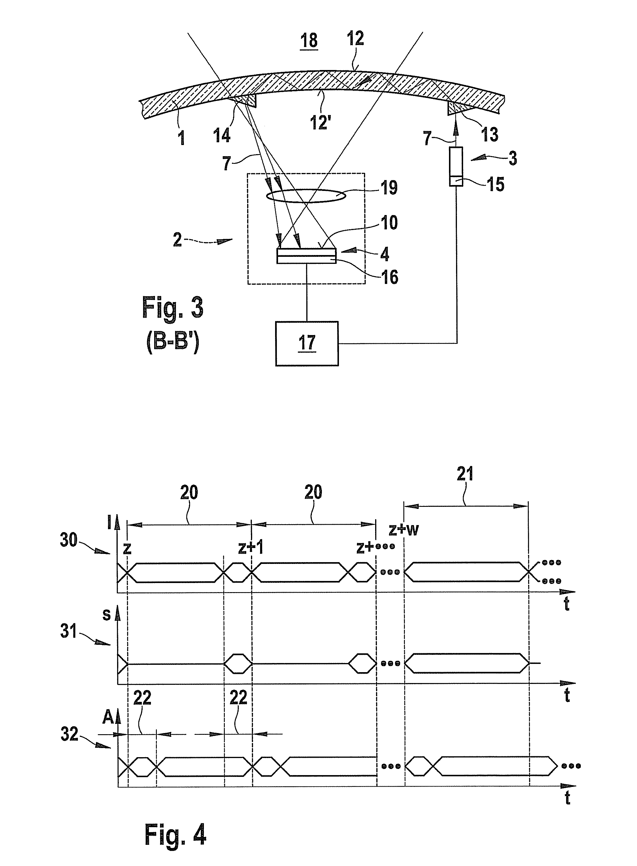
[0027]FIGS. 1 through 3 and FIG. 5 show one specific embodiment of a camera system according to the present invention for recording the surroundings of a vehicle and determining a state of a vehicle window pane 1, in the present case a windshield 1. FIG. 2 shows the section indicated by section line A-A′ in FIG. 1, and FIG. 3 shows the section indicated by section line B-B′.

[0028]The camera system includes a camera 2 and a radiation source 3. Camera 2 has an image sensor 4 for recording images with the aid of which a first optical radiation 6 generated by the vehicle surroundings is detectable. Radiation source 3 may generate a second optical radiation 7, a portion of which is likewise detectable by image sensor 4. This portion of second optical radiation 7 detected by image sensor 4 is a function of the state of window pane 1, in particular of wetting of window pan...


PUM

PropertyMeasurementUnit
optical radiationaaaaaaaaaa
areaaaaaaaaaaa
wettingaaaaaaaaaa

Abstract

A camera system for detecting the surroundings of a vehicle through a vehicle window pane (1), having a camera (2) having an image sensor (4), a first optical radiation (6) generated by the vehicle surroundings detectable by a sensor surface (10) of the image sensor (4), and a radiation source (3) for emitting a second optical radiation (7). At least a portion of the emitted second optical radiation (7) is detectable by the sensor surface (10) of the image sensor (4), and the portion of the second optical radiation (7) detected by the sensor surface (10) is a function of a state of window pane (1). The first and second optical radiation (6, 7) are jointly detectable via at least one partial area (8, 9) of the sensor surface (10). A method is also provided for detecting the surroundings of a vehicle employing the camera system.

Description

BACKGROUND OF THE INVENTION[0001]Cameras in vehicles for detecting the surroundings of a vehicle may be used in particular in driver assistance systems for functions such as night vision assistance, lane departure warning, traffic sign recognition, lighting assistance, and / or vehicle backup assistance.[0002]The use of cameras for rain sensor systems in vehicles is also known. Published German patent application document DE 197 49 33 A1 discloses a method and a camera for detecting objects, such as water droplets or other soiling, present on a windshield of a motor vehicle. The camera is situated behind the windshield and is focused on the exterior of the windshield.[0003]Camera systems are also known which are suitable for recording the surroundings of a vehicle as well as detecting a state of a vehicle window pane. Such a camera system is described in published German patent application document DE 10 2004 015 040 A1. This camera system includes a camera and a radiation source, the...

Claims


Application Information

Patent Timeline
Patent Type & Authority Patents(United States)
IPC IPC(8): B60S1/08G06K9/00G01N21/43B60R11/04B60Q1/00B60R11/00G01N21/85G01N21/55H04N7/18H01Q1/12
CPCB60R2011/0026G06K9/00791B60S1/0837H01Q1/1271B60S1/0822B60S1/0833B60S1/0818G01N2021/435B60S1/0844G01N21/552B60R11/04G06V20/56
Inventor SEGER, ULRICHFRANZ, GERALD
Owner ROBERT BOSCH GMBH
Why Eureka
Try Eureka