Deep-drawing device

a technology of drawing device and drawing surface, which is applied in the direction of stairway-like structures, building construction, construction, etc., can solve the problems of material deformation flow limit, which can contradict economic, industrial mass production, etc., and achieves the effect of facilitating and simplifying the withdrawal of workpieces, and facilitating and simplifying the manipulation process

Active Publication Date: 2014-12-23
INVENTIO AG
View PDF31 Cites 8 Cited by
  • Summary
  • Abstract
  • Description
  • Claims
  • Application Information

AI Technical Summary

Benefits of technology

[0007]The fulfillment of the object in accordance with the invention resides in the combination of deep-drawing with a prior adjustability and displaceability of the lamellar gaps of the tool from a receiving position to an end position for shaping the web profile or groove profile. The receiving position is so designed that a metal sheet or deep-draw metal sheet, which is shaped to be wavy or is profiled, is received by its wave valleys or profile valleys in the opened lamellar gaps corresponding with the receiving position. The subsequent adjustment of the tool from the receiving position to the end position means closing of the lamellar gaps, which produces a folding of the metal sheet or deep-draw metal sheet. The tool according to the invention thus stands in the end position, which provides, for the actual deep-drawing process, recesses corresponding with the projections. The simultaneous deep-drawing of each individual groove or each individual web is thereby possible. The metal sheet or deep-draw metal sheet, which lies with its eventual tread side downwardly in the deep-drawing device, thus has more material available. A multiple and tightly spaced deep-drawing taking place simultaneously is thereby newly possible.
[0008]This new method is faster and more economic than hitherto and offers increased reserves up to the tear strength limit.
[0009]Moreover, the accuracy of the end product or workpiece is increased, since the tolerances of each individual web, as disclosed in the specification JP-A-62270224, do not add together or summate. In the case of the new deep-drawing method according to the invention there are no summation tolerances from the individual production of the webs of the tread element or riser element, whereby there is also no need for costly re-finishing work or straightening work or calibrating work or rectification work.

Problems solved by technology

However, a general disadvantage of deep-drawing is that the necessary ‘material deformation flow limit’ can contradict economic, industrial mass production.

Method used


Image

  • Deep-drawing device
  • Deep-drawing device
  • Deep-drawing device

Examples


Embodiment Construction

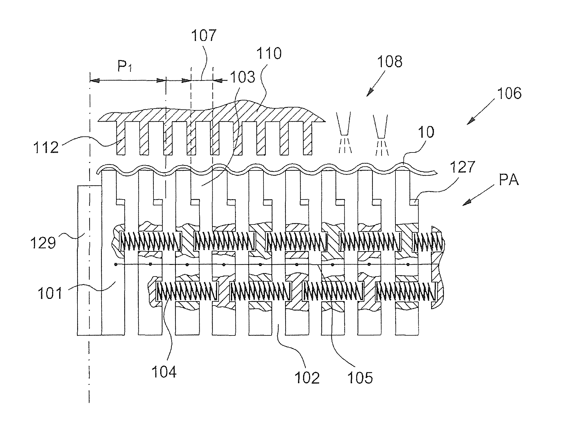
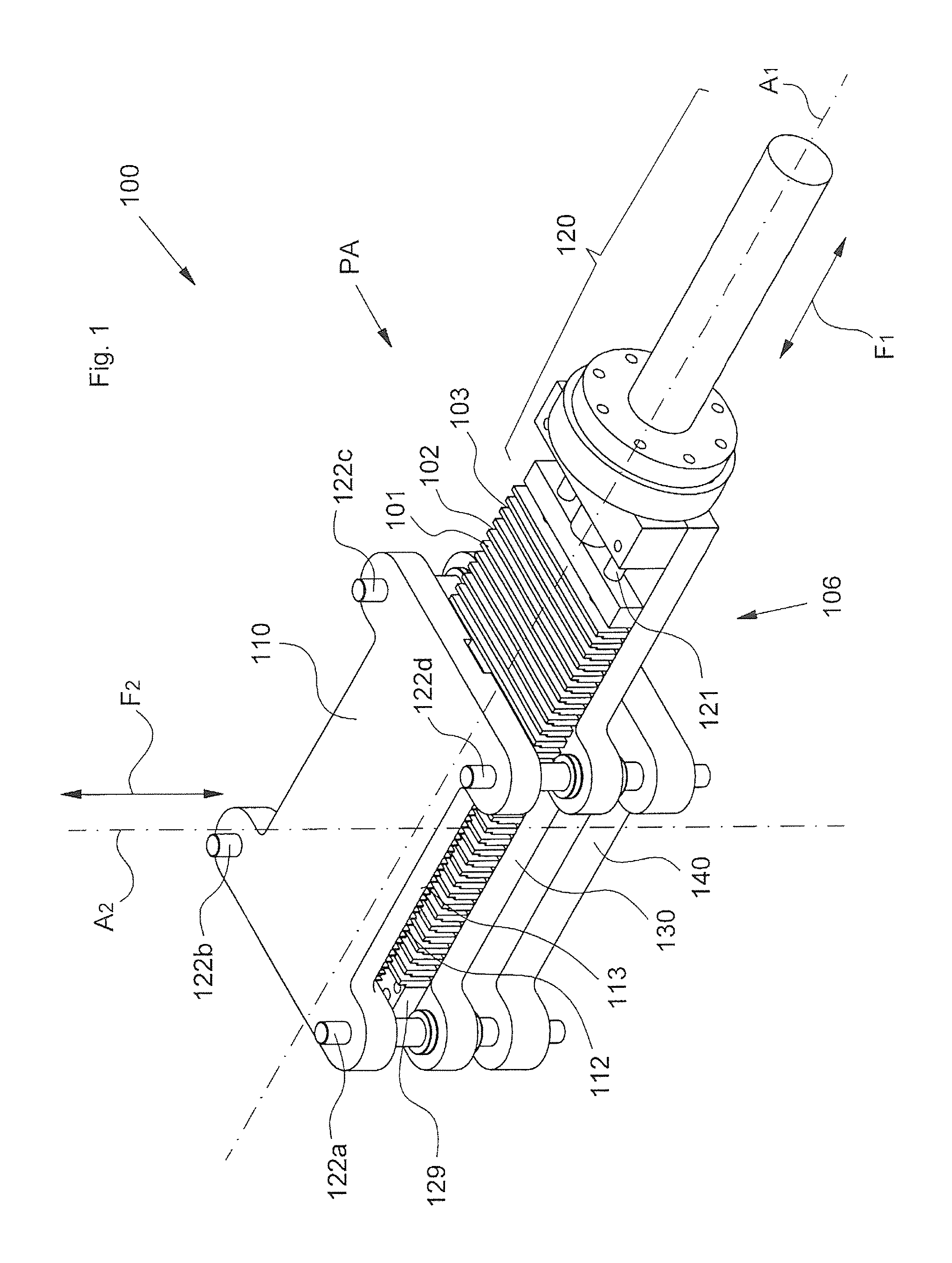
[0032]FIG. 1 shows schematically a deep-drawing device 100 according to the invention. A deep-drawing plate 110 with an underside 113, at which projections 112 are arranged, a counter-plate 130 and a base plate 140 are guided in common in guides 122a to 122d. A drive, which is not illustrated in more detail, acts by a drive force F2 along these guides 122a to 122d or along a deep-drawing axis A2 so that the deep-drawing plate 110 and the counter-plate 130 can be pressed relative to one another. A tool 106 comprises lamellae which in an open receiving position PA, shown here, of the tool 106 form lamellar gaps 102 or recesses 103. These lamellar gaps 102 are adjustable, because a ram 120 driven by a further, second drive (also not illustrated in more detail) so acts by a driving force F1 along a fold axis A1 perpendicular to the deep-drawing axis A2 that the lamellae 101 are movable along a lateral guide 121.

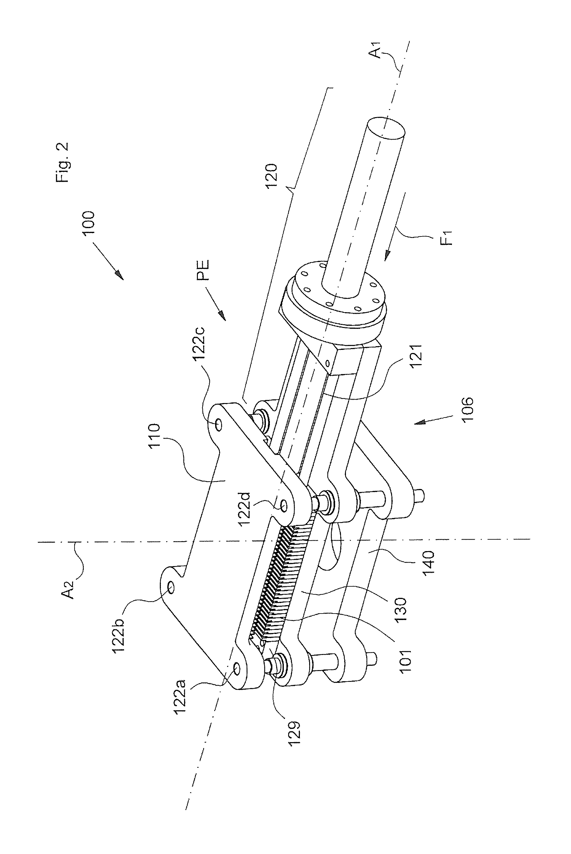
[0033]FIG. 2 shows schematically the deep-drawing device 100 according to th...


PUM

PropertyMeasurementUnit
angleaaaaaaaaaa
angleaaaaaaaaaa
angleaaaaaaaaaa

Abstract

The invention relates to a deep-drawing method and a corresponding deep-drawing device. The deep-drawing device has at least two projections (112) and at least two corresponding lamellar gaps (102) in a die (106), the width and positioning (Pi) of the lamellar gaps (102) being adjustable. Folding of a metal sheet (10) is brought about by closing the lamellar gaps (102). During the subsequent deep-drawing process, the projections (112) are lowered into corresponding recesses (103). Flat metal sheets (10) as well as previously corrugated metal sheets (10) can be folded and deep drawn by means of the deep-drawing device and the deep-drawing method.

Description

[0001]The present invention relates to a deep-drawing device and to a method with a corresponding deep-drawing device.BACKGROUND OF THE INVENTION[0002]By deep-drawing there is generally understood a compression-tension reshaping or compression reshaping of flatly shaped workpieces to form a hollow body open at one side or also only the shaping of bulges in the surface of the flatly shaped workpiece, in that a die presses the workpiece into a corresponding die plate.[0003]Deep-drawing in the last-mentioned form finds use in, for example, the production of steps or tread elements and riser elements of escalators or of plates of moving walkways. A tread element forms the tread surface or stand surface for a user of the escalator or of the moving walkway and a riser element forms the visible front face of the step in the inclined part of the escalator. Through the deep-drawing there is achieved, with the stated elements, the shaping of a web / groove profile which notwithstanding its low ...

Claims


Application Information

Patent Timeline
Patent Type & Authority Patents(United States)
IPC IPC(8): B21D13/02B21D13/00B21D22/26
CPCB21D22/26B21D13/02
Inventor MATHEISL, MICHAELNOVACEK, THOMASKHU, PETER
Owner INVENTIO AG
Why Eureka
Try Eureka