System and method for applying adhesive, buffer, and/or liner to I-joists

a technology of i-joists and buffers, applied in the field of automatic equipment, can solve the problems of significantly increasing construction costs, on-site manual application of liquid adhesives during floor construction, and inability to achieve the maximum sheer and strength of the finished construction project, etc., to achieve strong and consistent bonding, reduce noise, and reduce construction costs

Inactive Publication Date: 2014-12-23
ROBELL GLENN
View PDF3 Cites 9 Cited by
  • Summary
  • Abstract
  • Description
  • Claims
  • Application Information

AI Technical Summary

Benefits of technology

[0006]The primary object of this invention to provide a method and system used for automated enhancement of I-joists with an adhesive and / or buffer material layer and an optional protective release liner, with the adhesive and / or buffer material layer configured and dimensioned to achieve a stronger and more consistent bond between the I-joists and adjacent sheer panels commonly used in today's residential and commercial construction industry. Another object of this invention is to provide a method and system used for I-joist enhancement prior to its installation that produces adhesive-enhanced I-joists that meet local building codes for floor construction which require the use of adhesives, and does so with a very low cost when compared to the labor cost of manual adhesive application after I-joist installation. It is a further object of this invention to provide a method and system used for pre-installation I-joist enhancement that produces adhesive-enhanced I-joists that promptly bond with adjacent sheer panels, achieve a more consistent bond between I-joists and adjacent sheer panels in finished construction than manually applied adhesives, and are not compromised by I-joist installation during inclement weather. It is also an object of this invention to provide a method and system used for pre-installation I-joist enhancement with adhesive and / or buffer materials that assist noise abatement in finished construction.
[0007]The present invention method and system, when properly implemented, will provide I-joists enhanced with an adhesive and / or buffer material layer, and an optional protective release liner, that are able to achieve a more consistent bond with adjacent sheer panels to achieve maximum overall strength in finished construction for a very low cost when compared to the cost of on-site manual adhesive application. Such enhanced I-joists can be used in various parts of a building under construction, such as but not limited to floors, walls, decks, and / or roofs. It is contemplated for the adhesive layer and overlaying protective liner to be applied to at least one side of an I-joist flange by coordinated mechanical, electrical, and pneumatic components, which may be used as a stand-alone unit, or added to an I-joist manufacturing system, added to a saw system that converts raw I-joists from inventory to pre-cut sizes prior to shipment to a construction site or return to inventory, or added to a saw system that cuts routed patterns in I-joists for utility pass-through applications. Preferably when associated with a manufacturing or saw system, the present invention controller first accepts the cut patterns from the associated manufacturing or saw system controller. The associated manufacturing or saw system drive mechanism can also be used to begin transfer of a raw or pre-cut I-joist across the present invention system. In the alternative the present invention system can include an I-joist drive. An air-activated side pressure wheel in the present invention then pushes one flange of the I-joist to be enhanced against an opposing straight edge (which can be part of the manufacturing or saw system's in-feed or out-feed table assembly). Preferably, a low friction backing material is incorporated into or applied to the opposing straight edge, and / or one or more guide wheels are employed to reduce friction created by contact of the I-joist against the opposing straight edge. At least one present invention adhesive / glue head then extrudes glue / adhesive onto the exposed flange of the I-joist (that is in a remote position from the straight edge). Once the glue / adhesive / buffer is applied, a present invention liner applicator then places a protective liner upon the applied adhesive, glue, or buffer material. A present invention applicator roller bearing and a pressure roller bearing then press the adhesive / glue / buffer and the protective liner to the mil thickness desired, after which the present invention liner applicator cuts the protective liner at pre-determined points according to the cut pattern instructions received from the saw system's controller. If needed, a cooler can be used to cool the glue / adhesive / buffer material before the application of the release liner. An angled wheel in the present invention system then holds the enhanced I-joist in a fixed orientation so as to guide the I-joist to the saw system's routing and / or cutting stations and for optimum and expedient travel through the out-feed assembly of the present invention. As an alternative, the present invention improvement can be positioned after a manufacturing or saw system's routing and / or cutting stations, or between them if they are separate. It is contemplated for the present invention system to be located in an area where it is readily accessible for inspection, routine maintenance, and repair. A saw system typically used with the present invention improvement may exceed 130 feet in length and maintain a working height of approximately three feet, and further may have a controller, a saw and / or router, an inkjet system for applying markings to the flange end web, an in-feed table assembly, an out-feed table assembly, an air compressor, and a dust collector.

Problems solved by technology

However, there are at least two important disadvantages to the on-site manual application of liquid adhesives during floor construction.
One such disadvantage is that it is labor intensive and can significantly increase construction cost.
The second such disadvantage is that there is the potential for inconsistent application, whereby, if too little adhesive is used, maximum sheer and strength in the finished construction project is not achieved.
In the alternative, if too much adhesive is applied, material cost is unnecessarily increased.
In addition, weather conditions also can adversely affect the bonding of adhesives applied on site by interfering with its application or curing, or both.
Further, the cost of the automated application of the present invention adhesive and / or buffer layer and protective release liner to I-joists prior to their delivery to a construction jobsite is very low when compared to the on-site labor cost needed to achieve the enhanced strength in a finished floor that is mandated by most local codes.

Method used


Image

  • System and method for applying adhesive, buffer, and/or liner to I-joists
  • System and method for applying adhesive, buffer, and/or liner to I-joists
  • System and method for applying adhesive, buffer, and/or liner to I-joists

Examples


Embodiment Construction

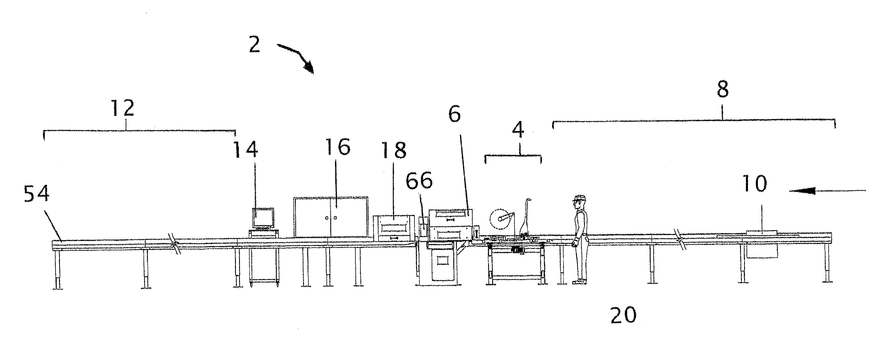
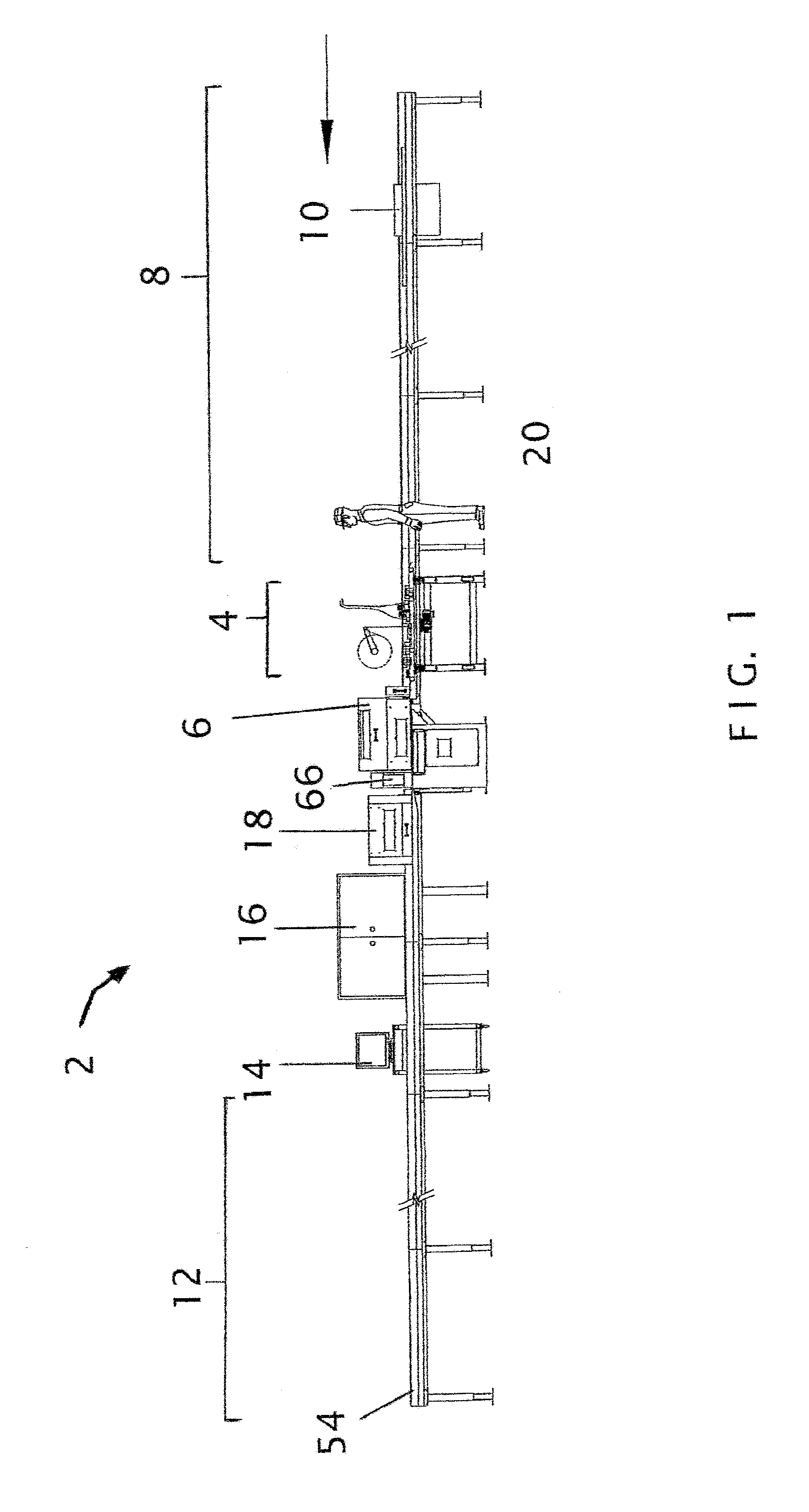
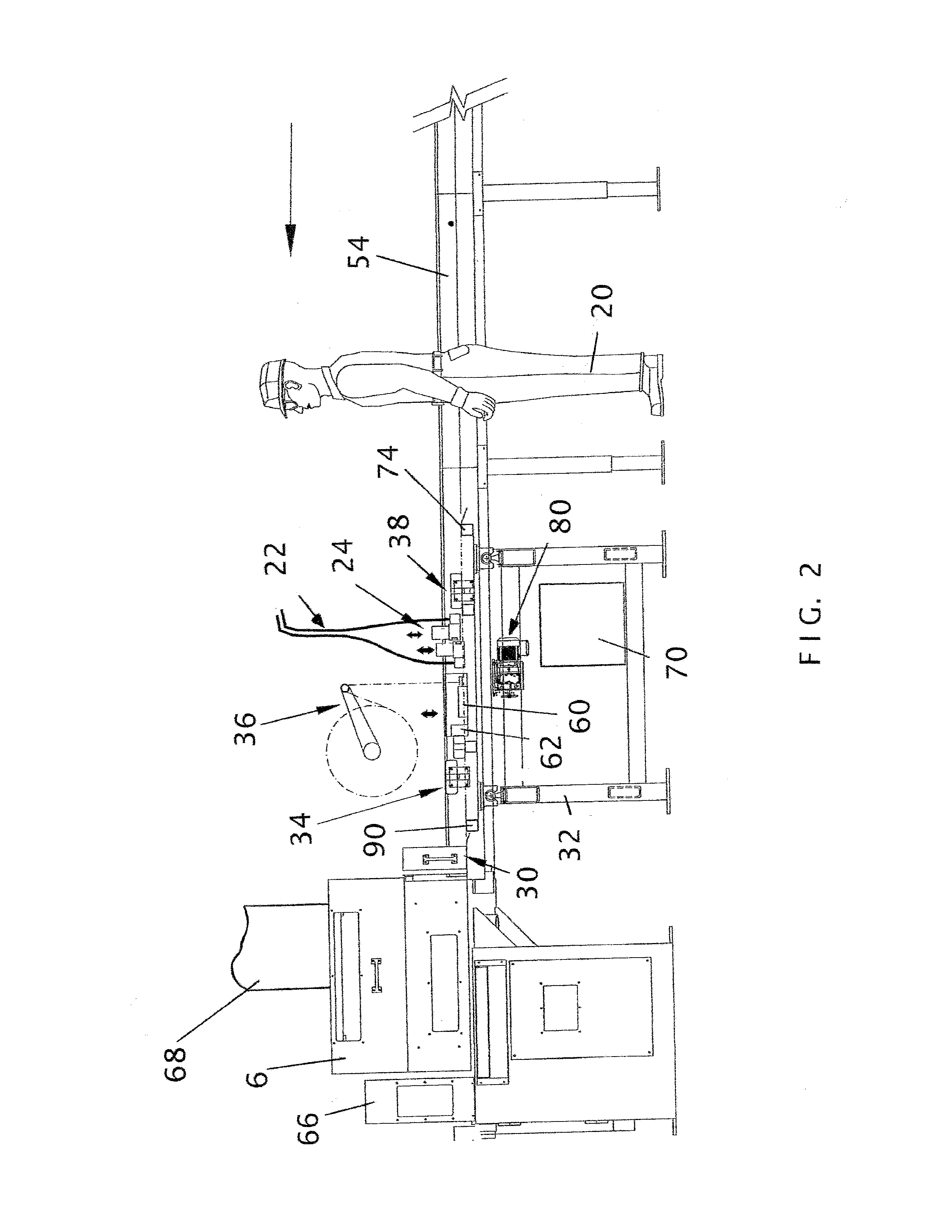
[0021]The present invention provides a system and method for producing value-added construction materials that achieve a more consistent bond between structural framing components, such as but not limited to smaller I-joist 44 and larger I-joist 42 in FIG. 3, and adjacent sheer panels (not shown) to achieve maximum overall strength in finished construction. When buffer materials are applied instead of glue or adhesive, or in combination therewith, noise in finished construction can be reduced. Typically, as a result of present invention system and method use, but not limited thereto, framing components, such as roof trusses, floor trusses, floor and ceiling joists, walls studs, roof and wall sheathing, and floor panels, will have adhesive (shown in FIG. 8 by the number 58) applied during manufacture to at least one surface, with the adhesive being configured and dimensioned to meet up with the intended contact area of the opposing component to which it will be joined after adhesive ...


PUM

PropertyMeasurementUnit
lengthaaaaaaaaaa
lengthaaaaaaaaaa
distanceaaaaaaaaaa

Abstract

A system and method for automated application of adhesive, buffer, and/or liner to I-joists, whereby a controlled amount of adhesive, glue, buffer material, and/or a protective liner, are successively applied to the exposed flange of an I-joist. An air-activated side pressure wheel first pushes one flange of an I-joist against an opposing friction-reduced straight edge, then at least one adhesive/glue head extrudes adhesive and/or buffer material onto the opposing exposed flange of the I-joist. An overhead liner applicator may then place a protective liner upon the applied adhesive and/or buffer material. An applicator roller bearing and a pressure roller bearing press the adhesive/buffer/liner to the desired mil thickness, after which the liner applicator cuts the protective liner according to the cut pattern instructions received from a controller. A cooler can be used to cool the adhesive/buffer before release liner application. The system may comprise coordinated mechanical, electrical, and pneumatic components.

Description

CROSS-REFERENCES TO RELATED APPLICATIONS[0001]This U.S. patent application is a Continuation-In-Part of U.S. patent application Ser. No. 11 / 640,020, now U.S. Pat. No. 7,918,960, filed by the same inventor on Dec. 15, 2006 for similar subject matter, and having the title of “Method and Improvement to Saw System Used for Cutting I-Joists to Size.” Thus, the inventor herein respectfully requests domestic priority for the current patent application herein based upon his previous U.S. patent application Ser. No. 11 / 640,020, now U.S. Pat. No. 7,918,960, filed in 2006.BACKGROUND[0002]1. Field of the Invention[0003]This invention relates generally to the field of automated equipment used to manufacture, rout, and / or cut I-Joists to size, specifically to a system and method for the automated application of buffer and / or adhesive material to I-joists prior to their installation at a construction site, whereby a controlled amount of material with adhesive and / or buffering capability, and an op...

Claims


Application Information

Patent Timeline
Patent Type & Authority Patents(United States)
IPC IPC(8): B32B37/26B23B37/00
CPCB29C63/02E04C3/14B23D45/003B32B37/26B29C63/0056B32B37/00B29C2063/485B29L2031/003Y10T156/1348Y10T156/1317B05C1/00B05D1/00Y10T156/1352Y10T156/12B27G11/00B27M3/0026Y10T156/1322E04C3/185
Inventor ROBELL, GLENN
Owner ROBELL GLENN
Why Eureka
Try Eureka