Press working die assembly

a technology of working die and assembly, applied in the field of die, can solve the problems of reducing the number of components required for restoring the rotary cam, reducing the cost, and preventing the rotation of the rotary cam completely, so as to achieve the effect of reducing the number of components and reducing the cos

Active Publication Date: 2014-12-30
YOURBUSINESS
View PDF12 Cites 0 Cited by
  • Summary
  • Abstract
  • Description
  • Claims
  • Application Information

AI Technical Summary

Benefits of technology

[0015]In addition, since the restoring action block is provided with the shock absorbing device that alleviates a shock generated at the time of collision at a portion abutting against the rotation impelling surface of the retracting slide block, the reciprocating driving apparatus such as the air cylinder can be protected. Then, the shock absorbing device can protect so that the force is applied to the center of a pressing and pulling action device, such as the air cylinder, as the drive unit in the reciprocating driving apparatus. In addition, with the provision of the shock absorbing member also at the distal end side of the slide block, the impact sound may be prevented and the slide block and the metal die can be protected. In this manner, the invention provides various advantageous effects.

Problems solved by technology

However, in press working die assemblies 1a and 1b in the prior art, since a pressure with which the pad 2 presses down is as large as several tens of ton, the structural strength against a force in the direction of rotation thereof is weak.
Therefore, it is structurally difficult for the press working die assemblies 1a and 1b to manufacture high quality products.
However, in this structure, setting of the rotating body 4c is achieved by the air cylinder 6, but the rotating body 4c cannot be restored to its original position.
However, this method has problems to be solved as described below.
1) Since the rotating body has to be held with pressurization of the spring, setting of the strength of the spring is difficult, and if the spring is too strong, the slide block can hardly be placed.
2) The cost is inevitably increased, and an installation space is also needed.

Method used


Image

  • Press working die assembly
  • Press working die assembly
  • Press working die assembly

Examples


Embodiment Construction

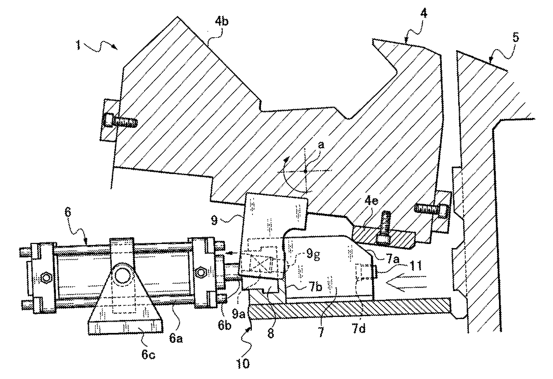
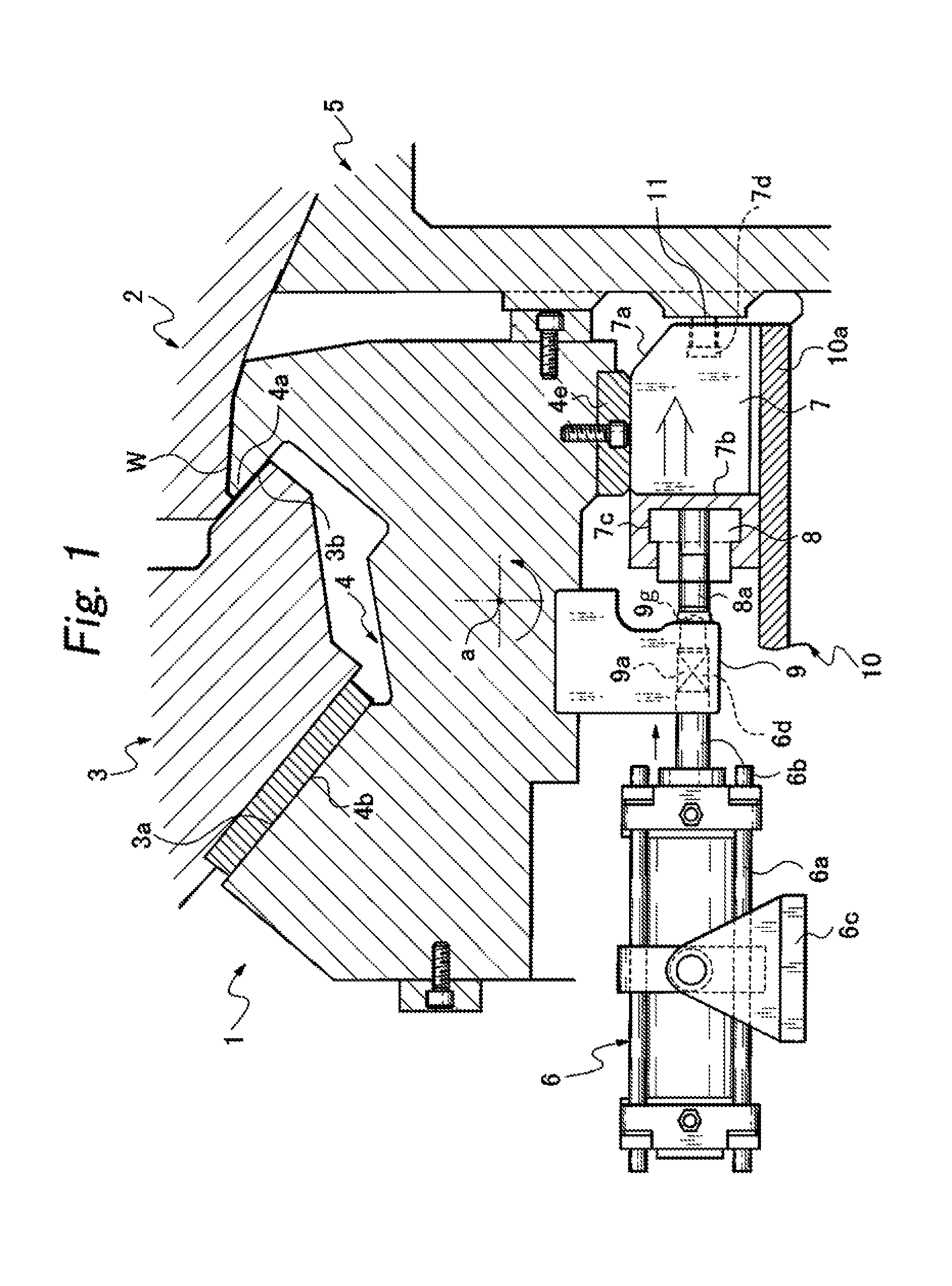
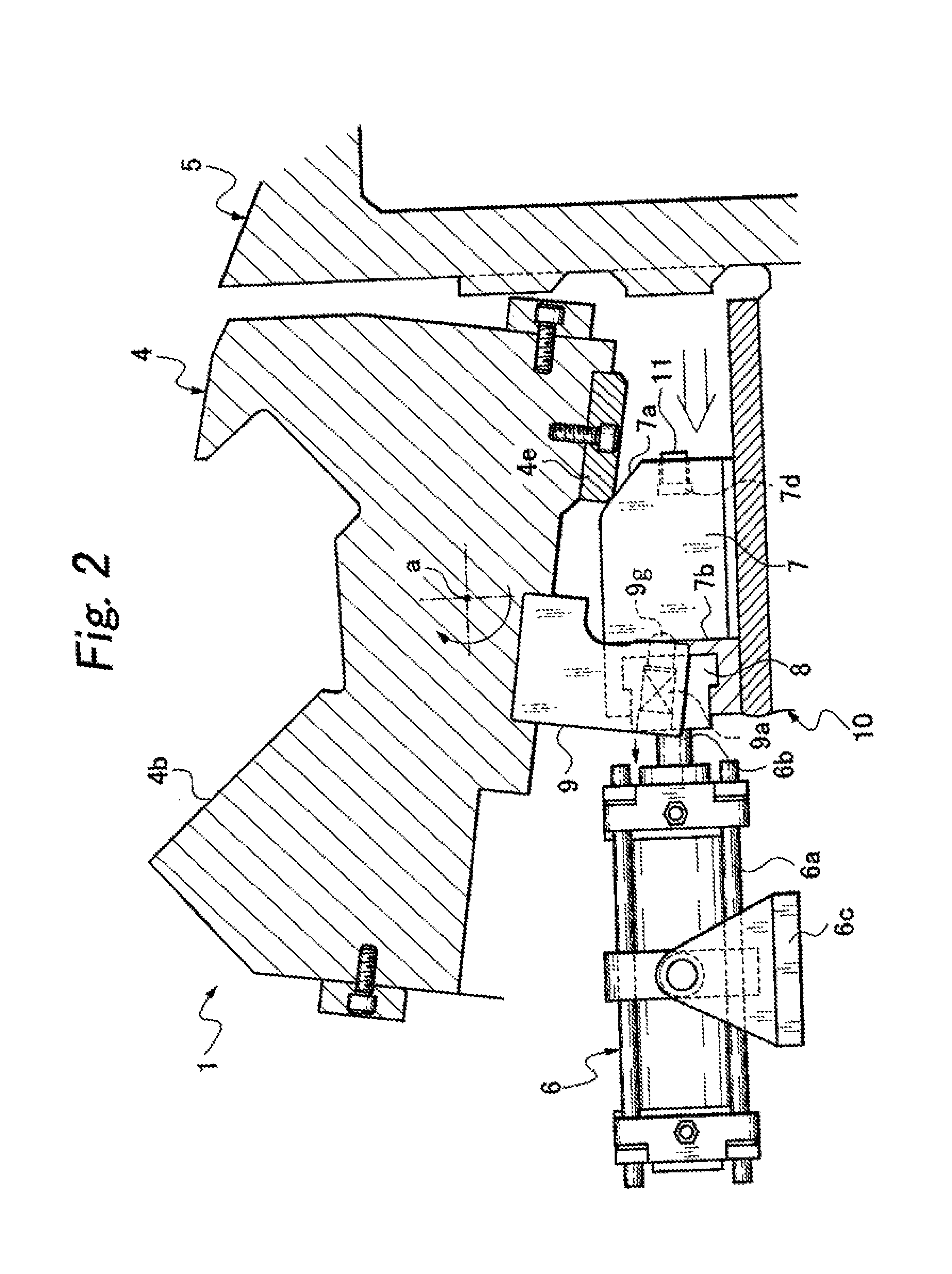
[0039]FIGS. 1 and 2 show a press working die assembly 1 according to an embodiment of the invention, which includes a pad 2 secured to an upper die holder (not shown) configured to be freely movable upward and downward for holding a workpiece W, a machining slide cam 3 supported on the upper die holder or a lower die holder so as to be slidable laterally along a cam surface 3a and including a bending edge 3b at an end thereof, a rotary cam 4 having a bending portion 4a for forming a negative angle portion of the workpiece W and a cam surface 4b for the slide cam 3, being rotatably supported on a lower die holder 10 entirely and rotated by an external force, and a reciprocating driving apparatus 6 configured to rotate the rotary cam 4 to a workpiece machining position.

[0040]The reciprocating driving apparatus 6 includes an air cylinder (driving unit) 6a, a piston rod (driven member) 6b, a supporting table 6c, a slide block 7, and a joint block 8. The air cylinder 6a is a trunnion typ...


PUM

PropertyMeasurementUnit
negative angleaaaaaaaaaa
rotationaaaaaaaaaa
anglesaaaaaaaaaa

Abstract

A press working die assembly includes a pad secured to an upper die holder so as to be movable upward and downward, a machining slide cam slidable laterally along a cam surface and having a bending edge at one end thereof, a rotatable rotary cam having a bending portion for forming a negative angle portion of a workpiece, and a reciprocating driving apparatus configured to rotate the rotary cam to a workpiece machining position. The reciprocating driving apparatus includes a slide block having a cam surface for rotating the rotary cam in a predetermined direction on an front end side and a rotation impelling surface configured to rotate the rotary cam back to its original position, and a restoring action block configured to come into abutment with the rotation impelling surface of the slide block when the slide block retracts to restore the rotary cam to its original position.

Description

BACKGROUND OF THE INVENTION[0001]1. Field of the Invention[0002]The present invention relates to a die for bending a panel edge portion such as for motor vehicles and, specifically, to a press working die assembly configured to be used for negative angle formation and to form a complex shape with a rotating body.[0003]2. Prior Art[0004]In the prior art, in the structure of a die assembly for forming portions having negative angles in a forming method using a press die assembly, for example, as shown in FIGS. 10A and 10B, a rotating body 4c is set to a lower die holder 10 body with an air cylinder 6 or the like. A pad 2 having a pressure source, which serves as a holder of a workpiece set in an upper die holder holds the rotating body 4c and a fixed punch 5. Then, a machining cam 3 moves forward and an edge portion of the workpiece is machined. In addition to a configuration in which the substantially L-shaped rotating body 4c rotationally moves about a point “a” as shown in FIGS. 10...

Claims


Application Information

Patent Timeline
Patent Type & Authority Patents(United States)
IPC IPC(8): B21D19/08B21D22/06B21J13/00B21D11/00
CPCB21D19/082B21D22/06B21D19/08B21D19/086B21D5/00B21D37/08B30B15/02
Inventor KINOSHITA, SHINJI
Owner YOURBUSINESS
Why Eureka
Try Eureka