
Scroll compressor

a compressor and scroll technology, applied in the direction of machines/engines, rotary/oscillating piston pump components, liquid fuel engines, etc., can solve the problems of deteriorating efficiency, increasing the power consumption of driving, and increasing the noise and vibration of the compressor, so as to prevent the damage of the scroll and prevent the sound of the impa

Active Publication Date: 2020-09-24
HANON SYST
View PDF0 Cites 0 Cited by
  • Summary
  • Abstract
  • Description
  • Claims
  • Application Information

AI Technical Summary

Benefits of technology

The present invention provides a scroll compressor with a buffer member that prevents damage to the scroll and reduces impact sound during operation. The buffer member is designed to move relative to the shaft and recess part, and can prevent the inner periphery of the recess part from coming in contact with the shaft during the compression of liquid refrigerant. The buffer member can also suppress an increase in inertial force and unbalance force of the rotating body due to the buffer member. Overall, the scroll compressor with the buffer member is more reliable and efficient during initial operation.

Problems solved by technology

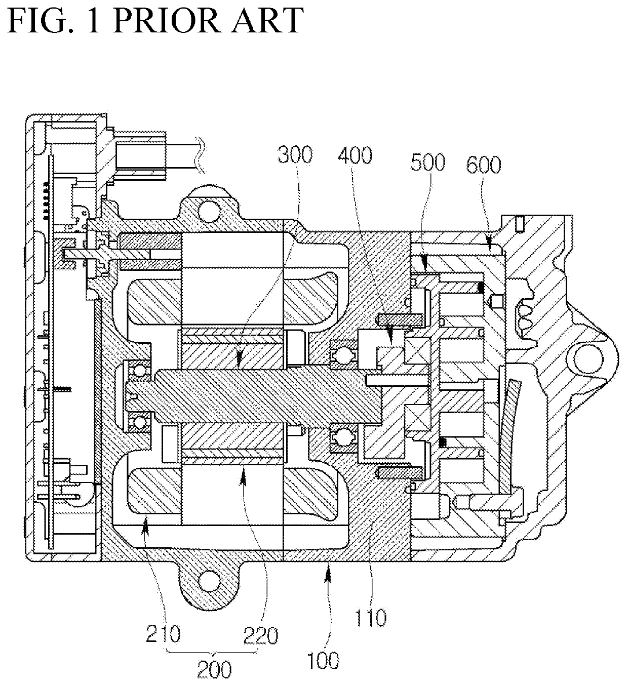
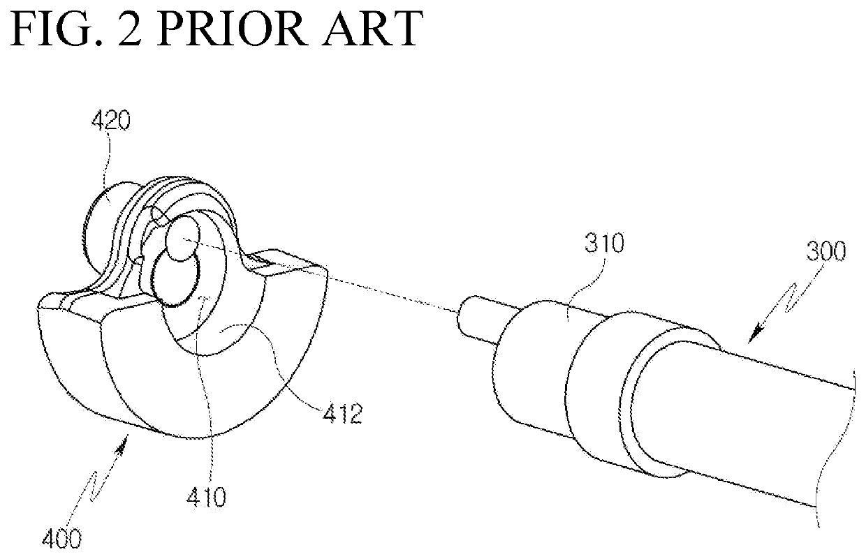
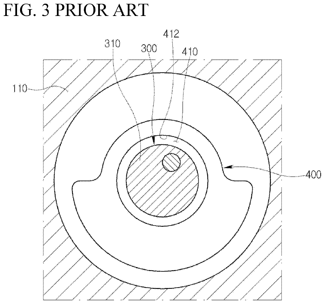
However, according to the scroll compressor in the related art, for example, if a compression reaction force is increased, or if the rotating speed of the shaft 300 is reduced or the rotation of the shaft 300 is interrupted, the eccentric bush 400 strikes a blow at the shaft 300 due to the rotational clearance as illustrated in FIG. 5, and thus an impact sound is generated to cause the problem that a noise and vibration of the compressor grow worse.
However, such a buffer member in the related art is fixed to any one of the shaft and the eccentric bush to increase an inertial force of a rotating body, and thus a power being consumed for driving is increased to deteriorate the efficiency.
Further, due to an increase of an unbalance force, a noise and vibration of a compressor grow worse.

Method used


Image

  • Scroll compressor
  • Scroll compressor
  • Scroll compressor

Examples


Embodiment Construction

[0051]Hereinafter, a scroll compressor according to the present disclosure will be described in detail with reference to accompanying drawings.

[0052]FIG. 6 is a cross-sectional view illustrating a scroll compressor according to an embodiment of the present disclosure, FIG. 7 is an exploded perspective view illustrating a shaft, an eccentric bush, and a buffer member in the scroll compressor of FIG. 6, and FIG. 8 is an enlarged cross-sectional view illustrating the shaft, the eccentric bush, and the buffer member of FIG. 7 in an assembled state. FIG. 9 is a cross-sectional view illustrating the positional relationship between a shaft, an eccentric bush, and a buffer member when the scroll compressor of FIG. 6 performs a normal operation, FIG. 10 is a cross-sectional view illustrating a rotated state of the eccentric bush of FIG. 9 based on the shaft caused by a rotational clearance, and FIG. 11 is a cross-sectional view illustrating a state where the eccentric bush of FIG. 10 is furt...


PUM


Abstract

A scroll compressor includes a shaft being rotated by a drive source, an eccentric bush including a recess part into which the shaft is inserted and an eccentric part being eccentric to the shaft, an orbiting scroll configured to perform an orbiting motion in interlock with the eccentric part, a fixed scroll tooth-engaged with the orbiting scroll, and a buffer member configured to prevent an outer periphery of the shaft and an inner periphery of the recess part from coming in contact with each other, wherein the buffer member is formed to be able to perform a relative motion with respect to the shaft and the recess part. Accordingly, the scrolls are prevented from being damaged, an impact sound is prevented from being generated, and an increase of an inertial force and an unbalance force of a rotating body is suppressed.

Description

CROSS-REFERENCE TO RELATED APPLICATION(S)[0001]This patent application claims priority to Korean Patent Application No. 10-2019-0032429 filed on Mar. 21, 2019, the entire disclosure of which is hereby incorporated herein by reference.FIELD[0002]Exemplary embodiments of the present disclosure relate to a scroll compressor, and more particularly, to a scroll compressor capable of compressing a refrigerant through a fixed scroll and an orbiting scroll.BACKGROUND[0003]In general, an air conditioner (A / C) for indoor cooling / heating is installed in a vehicle. Such an air conditioner includes a compressor that compresses a low-temperature low-pressure gaseous refrigerant input from an evaporator into a high-temperature high-pressure gaseous refrigerant and sends the compressed refrigerant to a condenser as a configuration of a cooling system.[0004]The compressor is classified into a reciprocating type that compresses the refrigerant in accordance with a reciprocating operation of a piston ...

Claims


Application Information

Patent Timeline
Patent Type & Authority Applications(United States)
IPC IPC(8): F04C15/00F04C2/02
CPCF04C15/0065F05B2260/96F04C2/025F05C2225/00F05C2251/10F05C2251/02F04C2240/605F04C18/0215F04C29/00F04C29/06F04C29/0021F04C2240/807F04C29/0057F04C29/0071F04C2240/60F04C2270/701F04C2210/26F05B2210/14F05B2260/962F05B2240/60F04C29/063
Inventor MOON, CHI MYEONGPARK, CHANG EONAHN, HYUN SEONG
Owner HANON SYST
Learn More