Hinge sealing element and an assembly including said element

a sealing element and sealing element technology, applied in the direction of heat reducing structures, fuselages, transportation and packaging, etc., can solve the problems of reducing efficiency, generating excessive noise, gap formation in the top skin surface between the spoiler,

Inactive Publication Date: 2014-12-30
AIRBUS OPERATIONS LTD
View PDF27 Cites 18 Cited by
  • Summary
  • Abstract
  • Description
  • Claims
  • Application Information

AI Technical Summary

Benefits of technology

[0009]According to the invention, there is provided a hinge sealing element to substantially prevent airflow between a leading edge of a moveable aero surface structure and an edge of a fixed skin of an aircraft wing in the vicinity of the ribs to which the aero surface structure is pivotally mounted, the hinge sealing element comprising a deformable elongate, resiliently flexible strip having an upper face to contact an edge of a fixed skin and one end attachable to a moveable aero surface structure such that said strip extends from an upper surface of said moveable aero surface structure beyond its leading edge and into a space between the trailing edge of the fixed skin and the rib of the aircraft wing to a second, free end, the strip being configured such that it deforms during pivotal movement of the moveable aero surface structure to maintain contact between the upper face of the flexible strip and the trailing edge of the fixed skin.
[0011]According to the invention, there is also provided an assembly to substantially prevent airflow between a leading edge of a moveable aero surface structure and an edge of a fixed skin of an aircraft wing in the vicinity of the ribs to which the moveable aero surface structure is pivotally mounted, including the hinge sealing element according to any preceding claim.
[0012]The present invention provides improved sealing between the edge of the moveable aero surface structure and the edge of the fixed wing in the region where the moveable aero surface structure is hingedly mounted to the fixed wing, throughout the full range of deployment of the moveable aero surface structure.
[0015]Preferably, a cap is attached to the free end of the hinge sealing element to reduce friction between the sealing element and the fixed wing where the free end of the hinge sealing element contacts the fixed wing during pivotal movement of the aero surface structure. Or as an alternative the material itself could be folded over on itself to provide for a ‘safe edge’.

Problems solved by technology

Although spoilers may only droop by an angle of up to 15 degrees to aid lift, providing for the droop function results in gaps being formed in the top skin surface between the spoiler and the trailing edge of the fixed wing at all the positions where the spoiler is hingedly mounted to the fixed wing during cruise.
These gaps result in the generation of excessive noise and reduce efficiency which is unacceptable, especially now that there are increasingly more stringent requirements for noise reduction in populated areas as well as demands for more efficient aircraft.
In larger aircraft the additional noise generated as a result of the formation of gaps in the hinge area is particularly noticeable, as such aircraft can have up to seven spoilers per wing with a minimum of two hinges per spoiler.
Although conventional elastomeric materials are often employed for the purpose of sealing between a spoiler and the fixed wing, it has been found that this type of seal is not feasible considering the range of movement throughout which sealing is required when a spoiler is required to droop to aid lift in addition to its normal function of raising to spoil lift.

Method used


Image

  • Hinge sealing element and an assembly including said element
  • Hinge sealing element and an assembly including said element
  • Hinge sealing element and an assembly including said element

Examples


Embodiment Construction

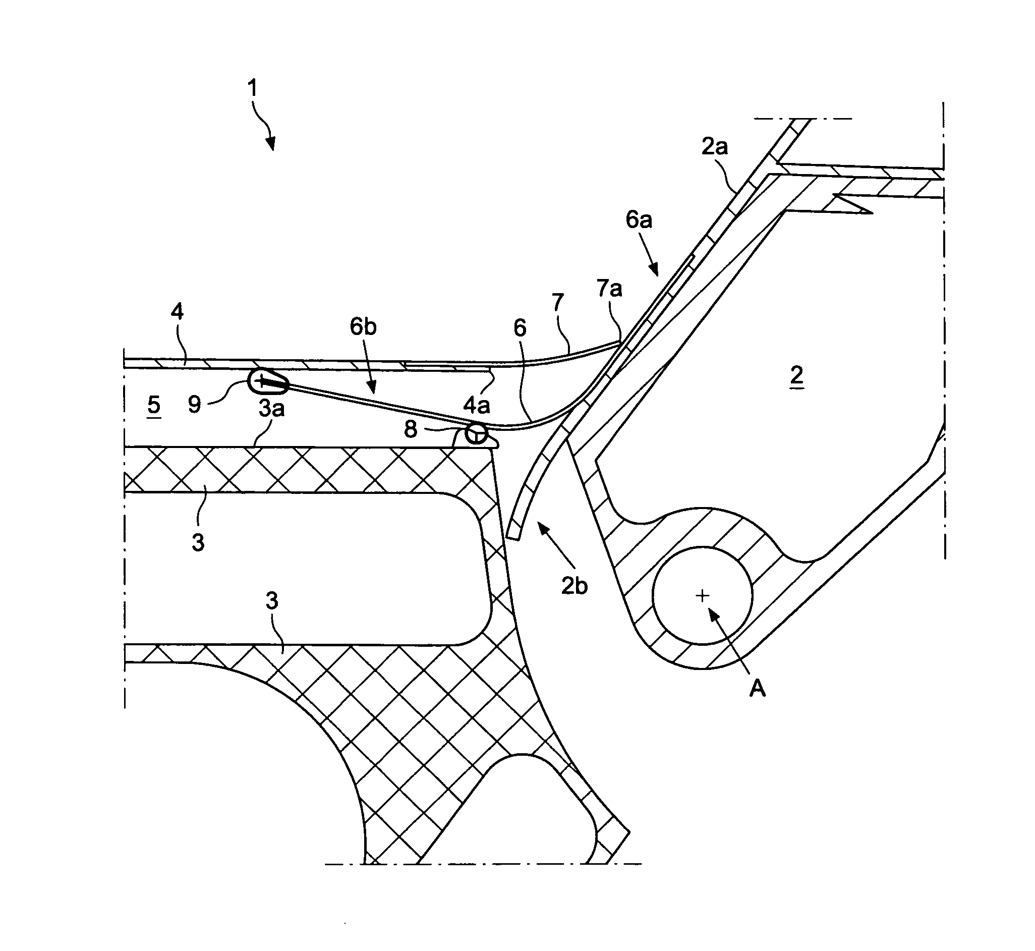
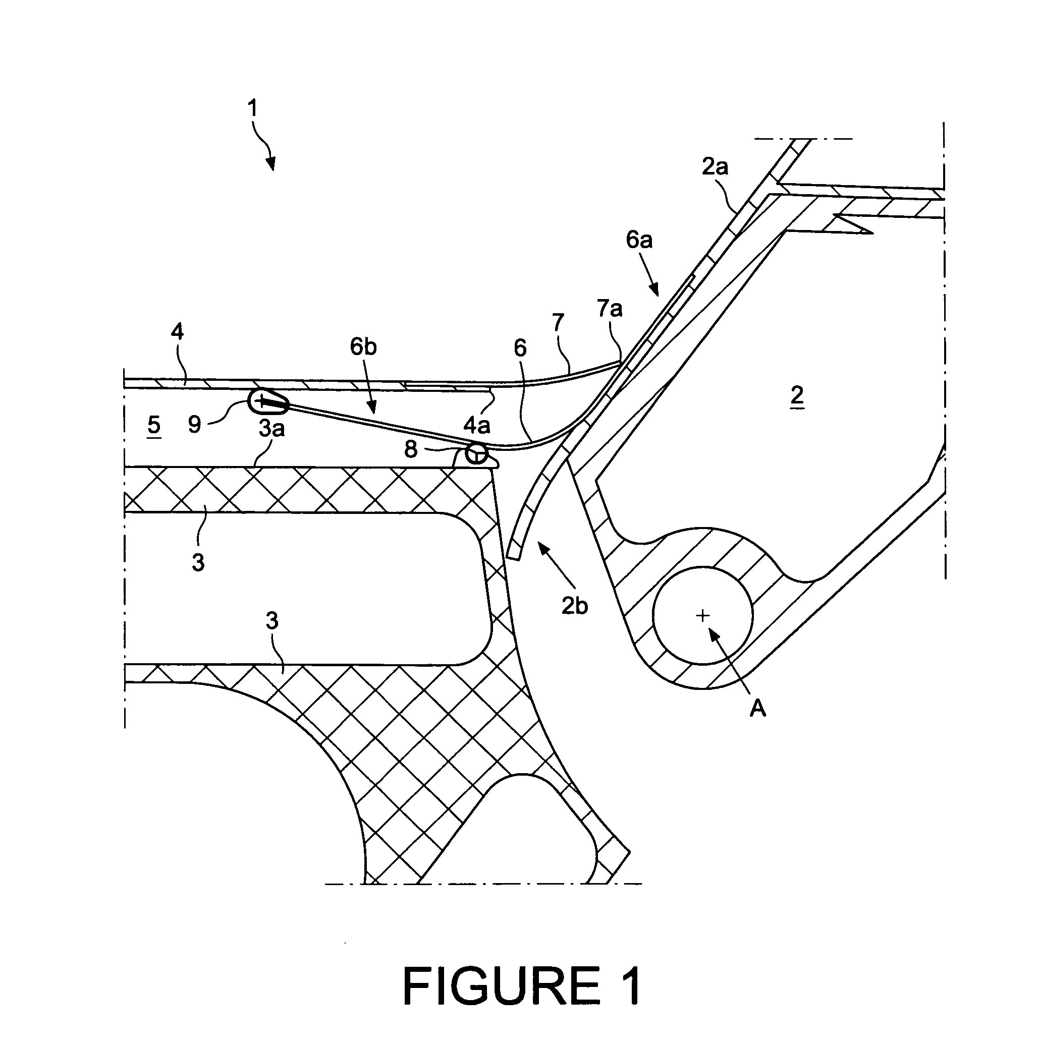
[0028]Although the description primarily makes reference to a hinge seal applied between a spoiler and a fixed wing of an aircraft, it is equally applicable to ailerons to improve aero efficiency and reduce noise. It may also be applied to flap hinge fairings to improve aero efficiency (reduced drag in high lift) and reduce noise. Referring now to the drawings, there is shown in FIG. 1 a cross-sectional view through a portion of a fixed wing 1 of an aircraft to which a spoiler 2 is mounted. The fixed wing 1 has a plurality of internal structural ribs 3 (one of which is shown in FIGS. 1 and 2) spaced from each other along the length of the wing 1 and to which each spoiler 2 is pivotally mounted for movement about a pivot point A. In FIG. 1, the spoiler 2 is shown in its fully raised position (around 55 degrees) to spoil lift. The fixed wing 1 has an upper skin 4 which is spaced from the rib 3 to provide a gap 5 between the skin 4 and the rib 3.

[0029]A resiliently deformable sealing e...


PUM


Abstract

A hinge sealing element to substantially prevent airflow between an edge of a moveable aero surface structure and an edge of a fixed skin of an aircraft wing in the vicinity of the ribs to which the moveable aero surface structure is pivotally mounted is disclosed. The hinge sealing element comprising a deformable elongate, resiliently flexible strip having an upper face to contact a trailing edge of a fixed skin and one end attachable to a moveable aero surface structure such that said strip extends from an upper surface of said moveable aero surface structure beyond its leading edge and into a space between the edge of the fixed skin and the rib of the aircraft wing to a second, free end. The strip is configured such that it deforms during pivotal movement of the moveable aero surface structure to maintain contact between the upper face of the flexible element and the trailing edge of the fixed skin.

Description

[0001]This application claims priority to GB 0908370.0 filed 15 May 2009, the entire contents which is hereby incorporated by reference.INTRODUCTION[0002]The present invention relates to a hinge sealing element and to an assembly that includes the hinge sealing element of the invention. More specifically, the invention relates to a sealing element to substantially prevent airflow between a leading edge of a moving aero surface structure of a wing, such as a spoiler or aileron, and an edge of a fixed skin of an aircraft wing in the vicinity of the ribs to which the moving surface structure is pivotally mounted.BACKGROUND[0003]A spoiler is a type of moving surface structure which is used to break up the airflow around an aerodynamic surface such as an aircraft wing, in order to slow the movement of the aircraft through the air or to decrease the lift on the surface. On the majority of large aircraft, conventional spoilers are stowed flat to the wing outer mould line during cruise and ...

Claims


Application Information

Patent Timeline
Patent Type & Authority Patents(United States)
IPC IPC(8): B64C3/50B64C3/36B64C7/00B64C9/02
CPCB64C7/00B64C9/02Y02T50/32Y02T50/44Y02T50/30Y02T50/40
Inventor PARKER, SIMON JOHN
Owner AIRBUS OPERATIONS LTD
Why Eureka
Try Eureka