Check patentability & draft patents in minutes with Patsnap Eureka AI!

Minimizing the use of chip routing resources when using timestamped instrumentation data by transmitting the most significant bits of the timestamp in series and transmitting the least significant bits of the timestamp in parallel

a technology of timestamped instrumentation and chip routing resources, applied in the direction of instruments, computer aided design, generating/distributing signals, etc., can solve the problems of reducing physical access to circuits for test and emulation, unable to achieve basic necessity for complex designs, and insufficient method to provide a high level of detectable fault coverag

Active Publication Date: 2014-12-30
TEXAS INSTR INC
View PDF6 Cites 0 Cited by
  • Summary
  • Abstract
  • Description
  • Claims
  • Application Information

AI Technical Summary

Problems solved by technology

Diminished physical access to circuits for test and emulation is an unfortunate consequence of denser designs and shrinking interconnect pitch.
This basic necessity is difficult to achieve for complex designs without taking testability into account in the logic design phase so automatic test equipment can test the product.
For very large systems this method proves inadequate in providing a high level of detectable fault coverage.
Another problem in large designs is the long time and substantial expense involved in design for test.
Without a proactive testability, simulation and emulation plan, a large amount of subsequent design time would be expended on test pattern creation and upgrading.
Even if a significant investment were made to design a module to be reusable and to fully create and grade its test patterns, subsequent use of a module may bury it in application specific logic.
This would make its access difficult or impossible.
The advances of IC design are accompanied by decreased internal visibility and control, reduced fault coverage and reduced ability to toggle states, more test development and verification problems, increased complexity of design simulation and continually increasing cost of CAD (computer aided design) tools.
In the board design the side effects include decreased register visibility and control, complicated debug and simulation in design verification, loss of conventional emulation due to loss of physical access by packaging many circuits in one package, increased routing complexity on the board, increased costs of design tools, mixed-mode packaging, and design for produceability.
In application development, some side effects are decreased visibility of states, high speed emulation difficulties, scaled time simulation, increased debugging complexity, and increased costs of emulators.
Production side effects involve decreased visibility and control, complications in test vectors and models, increased test complexity, mixed-mode packaging, continually increasing costs of automatic test equipment and tighter tolerances.
Increasing clock rates mean that emulation support logic causes increased electrical intrusiveness.
More sophisticated packaging causes emulator connectivity issues.
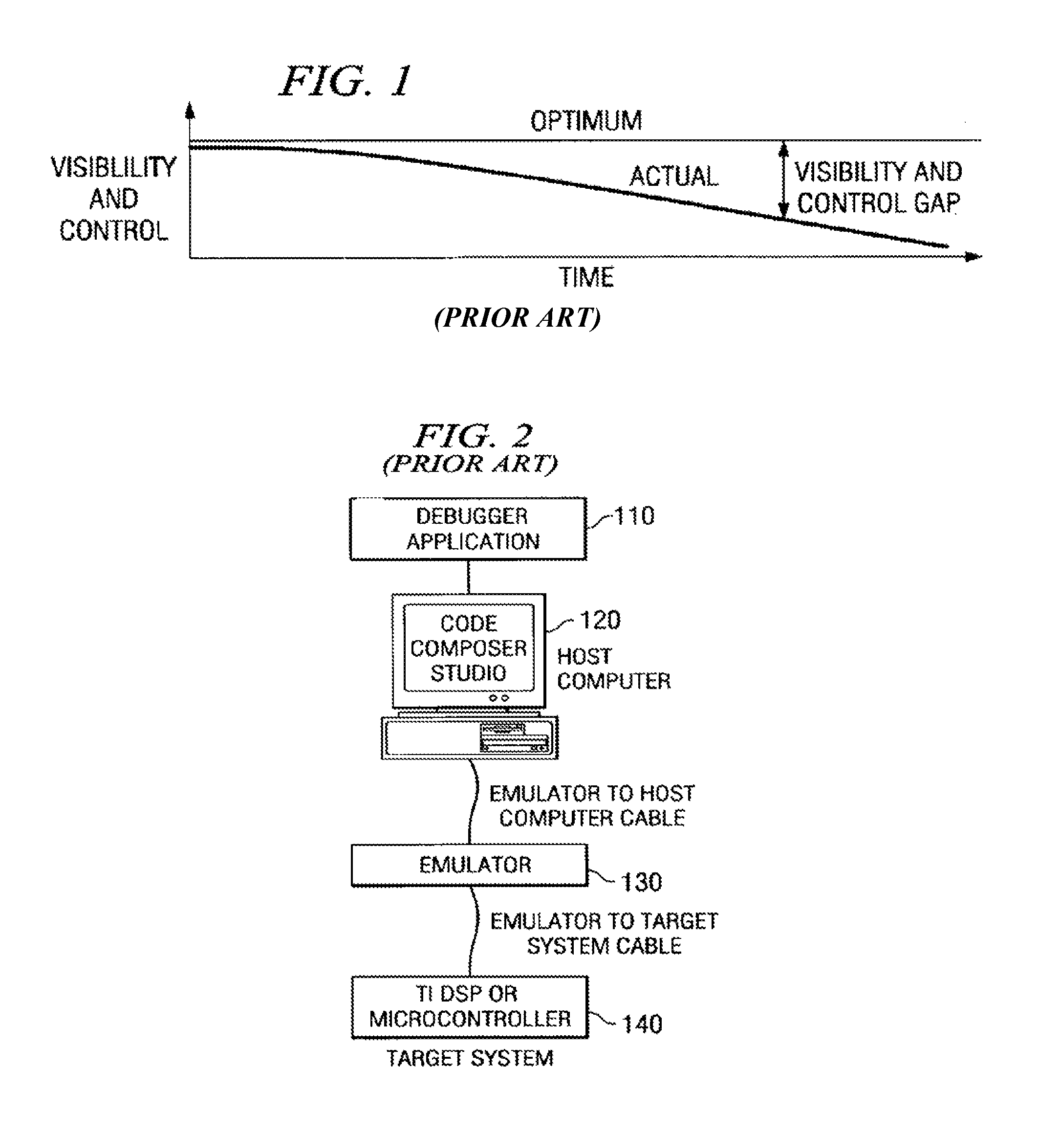
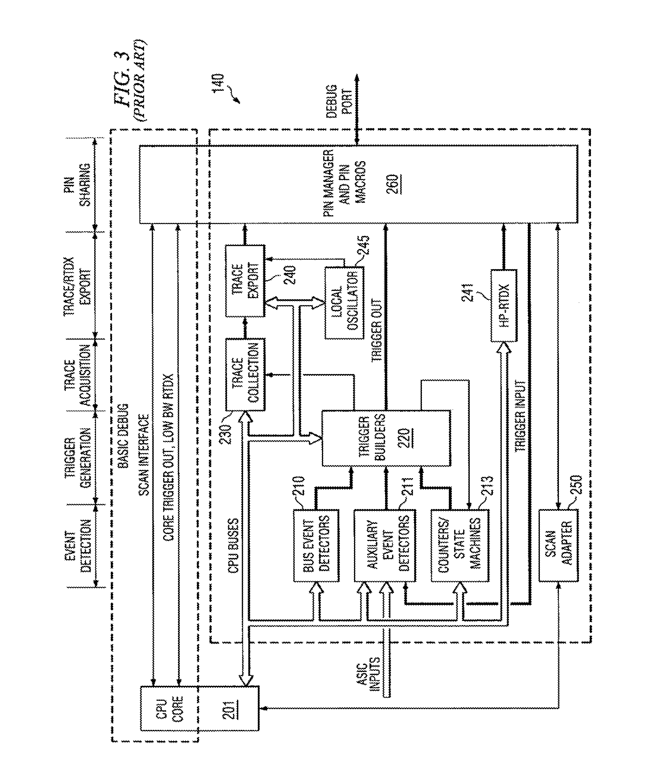
Today these same factors, with new twists, are challenging the ability of a scan based emulator to deliver the system debug facilities needed by today's complex, higher clock rate, highly integrated designs.
Each of these positive system trends adversely affects the observation of system activity, the key enabler for rapid system development.
The steady progression of integration levels and increases in clock rates steadily decrease the actual visibility and control available over time.
Traditional debug options such as logic analyzers and partitioned prototype systems are unable to keep pace with the integration levels and ever increasing clock rates of today's systems.
As integration levels increase, system buses connecting numerous subsystem components move on chip, denying traditional logic analyzers access to these buses.
With limited or no significant bus visibility, tools like logic analyzers cannot be used to view system activity or provide the trigger mechanisms needed to control the system under development.
A loss of control accompanies this loss in visibility, as it is difficult to control things that are not accessible.
This approach is also under siege from the ever-increasing march of system clock rates.
As the central processing unit (CPU) clock rates increase, chip to chip interface speeds are not keeping pace.
Developers find that a partitioned system's performance does not keep pace with its integrated counterpart, due to interface wait states added to compensate for lagging chip to chip communication rates.
At some point, this performance degradation reaches intolerable levels and the partitioned prototype system is no longer a viable debug option.
Increasing CPU clock rates are also limiting availability of other simple visibility mechanisms.
Since the CPU clock rates can exceed the maximum I / O state rates, visibility ports exporting information in native form can no longer keep up with the CPU.
These developments mean simple visibility ports can no longer be counted on to deliver a clear view of CPU activity.
As visibility and control diminish, the development tools used to develop the application become less productive.
The tools also appear harder to use due to the increasing tool complexity required to maintain visibility and control.
The visibility, control, and ease of use issues created by systems-on-a-chip tend to lengthen product development cycles.
Even as the integration trends present developers with a tough debug environment, they also present hope that new approaches to debug problems will emerge.
As high speed, high performance chips are increasingly dominated by very large memory structures, the system cost associated with the random logic accompanying the CPU and memory subsystems is dropping as a percentage of total system cost.
The incremental cost of several thousand gates is at an all time low.
Since these on-chip capabilities affect the chip's recurring cost, the scalability of any solution is of primary importance.
This emulation technology may impose restrictions on the placement of chip debug pins, board layout, and requires precise pin timings.
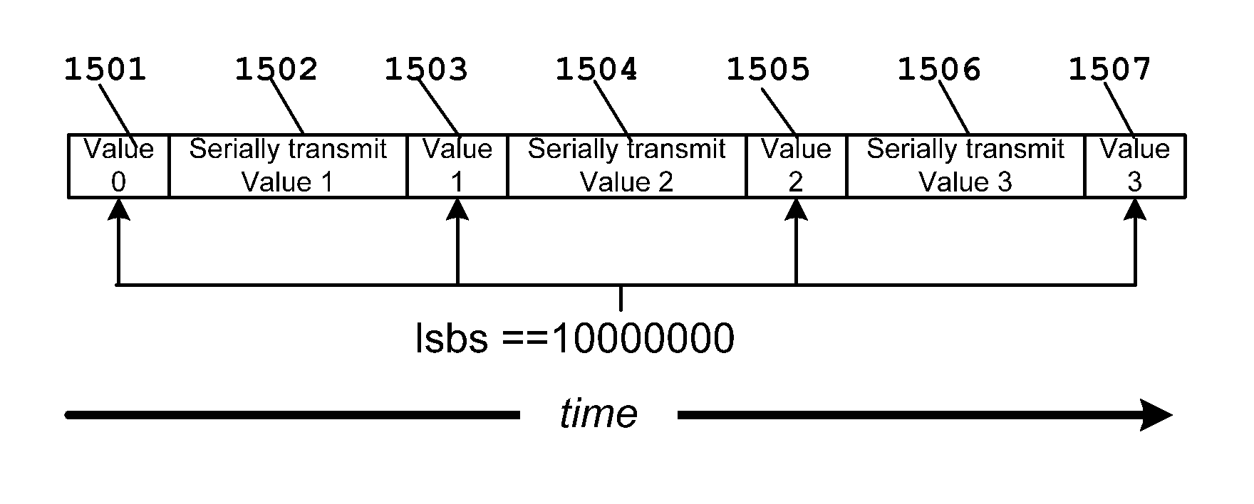
Method used


Image

  • Minimizing the use of chip routing resources when using timestamped instrumentation data by transmitting the most significant bits of the timestamp in series and transmitting the least significant bits of the timestamp in parallel
  • Minimizing the use of chip routing resources when using timestamped instrumentation data by transmitting the most significant bits of the timestamp in series and transmitting the least significant bits of the timestamp in parallel
  • Minimizing the use of chip routing resources when using timestamped instrumentation data by transmitting the most significant bits of the timestamp in series and transmitting the least significant bits of the timestamp in parallel

Examples


Embodiment Construction

[0053]FIG. 3 illustrates an example of one on-chip debug architecture embodying target system 140. The architecture uses several module classes to create the debug function. One of these classes is event detectors including bus event detectors 210, auxiliary event detectors 211 and counters / state machines 213. A second class of modules is trigger generators including trigger builders 220. A third class of modules is data acquisition including trace collection 230 and formatting. A fourth class of modules is data export including trace export 240, and real-time data exchange export 241. Trace export 240 is controlled by clock signals from local oscillator 245. Local oscillator 245 will be described in detail below. A final class of modules is scan adaptor 250, which interfaces scan input / output to CPU core 201. Final data formatting and pin selection occurs in pin manager and pin micros 260.

[0054]The size of the debug function and its associated capabilities for any particular embodi...


PUM


Abstract

A timestamp generator generates a timestamp value having a predetermined number of most significant bits and a predetermined number of least significant bits. The least significant bits are transmitted to a client via a parallel data bus. The most significant bits are transmitted to the client sequentially via a series data bus. Each client receives the parallel least significant bits and the series most significant bits and assembles a complete time stamp value.

Description

CLAIM OF PRIORITY[0001]This application claims priority under 35 U.S.C. 119(e)(1) to U.S. Provisional Application No. 61 / 287,289 filed Dec. 17, 2009.TECHNICAL FIELD OF THE INVENTION[0002]The technical field of this invention is time stamping for emulation and debug of electronic systems.BACKGROUND OF THE INVENTION[0003]Advanced wafer lithography and surface-mount packaging technology are integrating increasingly complex functions at both the silicon and printed circuit board level of electronic design. Diminished physical access to circuits for test and emulation is an unfortunate consequence of denser designs and shrinking interconnect pitch. Designed-in testability is needed so the finished product is both controllable and observable during test and debug. Any manufacturing defect is preferably detectable during final test before a product is shipped. This basic necessity is difficult to achieve for complex designs without taking testability into account in the logic design phase ...

Claims


Application Information

Patent Timeline
Patent Type & Authority Patents(United States)
IPC IPC(8): G06F1/04G06F13/38G06F1/14
CPCG06F1/04G06F13/38G06F1/14G06F2217/14G06F17/5031G06F2217/62G06F2217/84G06F30/3312G06F30/333G06F30/396G06F2119/12G06F30/398Y02T10/82
Inventor SWOBODA, GARY, L.
Owner TEXAS INSTR INC
Features
  • R&D
  • Intellectual Property
  • Life Sciences
  • Materials
  • Tech Scout
  • Unparalleled Data Quality
  • Higher Quality Content
  • 60% Fewer Hallucinations
Learn More