Wear assembly

a technology of wear components and wear parts, applied in the field of wear components and wear components, can solve the problems of extreme stress within the components, wear members can be worn away quickly, and excavated materials are abrasive, so as to reduce the risk of damaging the underlying support structure, reduce the risk of welding, and speed up the removal and attachment.

Inactive Publication Date: 2015-01-06
ESCO GRP LLC
View PDF26 Cites 43 Cited by
  • Summary
  • Abstract
  • Description
  • Claims
  • Application Information

AI Technical Summary

Benefits of technology

[0008]In one aspect of the invention, a wear component for earthmoving equipment is provided with a mounting portion, a working portion and a strain relief area between the mounting portion and the working portion. The mounting portion is fixed to the equipment. The working portion operates as a seat for a wear member or a wear surface to contact the ground. The strain relief area is provided between the two portions to permit sufficient flexibility to reduce the risk of cracking or failing of the fixed attachment on account of the applied loads. This enables greater reliability in the wear components and generally a longer usable life.
[0016]In another aspect of the invention, a wear component for earthmoving equipment is provided with a pair of mounting portions and a medial working portion. The mounting portions are defined at opposite ends of the wear component and are welded to the underlying support. In one example, the underlying support could be a lip of an excavating bucket, but it could be other surfaces subjected to earthen materials. In the various applications, the working portion remains free of being welded to the underlying support. This arrangement requires less welding so as to speed removal and attachment, and reduces the risk of damaging the underlying support structure (such as a lip), while still maintaining a secure attachment of the wear component (whether it be a base or wear member) to the underlying support.

Problems solved by technology

Excavated materials are abrasive and the wear members can be worn away quickly.
Stress within the components can be extreme even with very large components and design of a component requires balancing of strength and ductility.
Excessive stiffness or brittleness of the components can induce cracking at critical points of the assemblies such as welds and sharp inside corners.
This results in a decrease in stiffness in the strain relief area in contrast to the balance of the component.

Method used


Image

  • Wear assembly
  • Wear assembly
  • Wear assembly

Examples


Embodiment Construction

[0030]FIGS. 1-5 illustrate a preferred embodiment of the invention. FIGS. 6-12 show alternative embodiments.

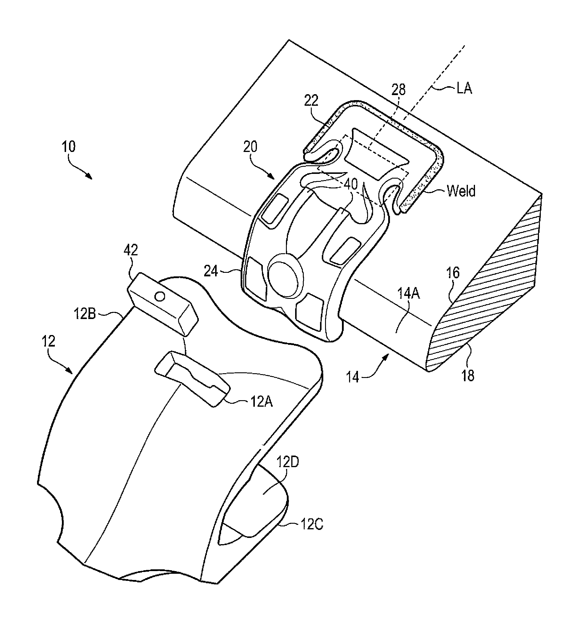
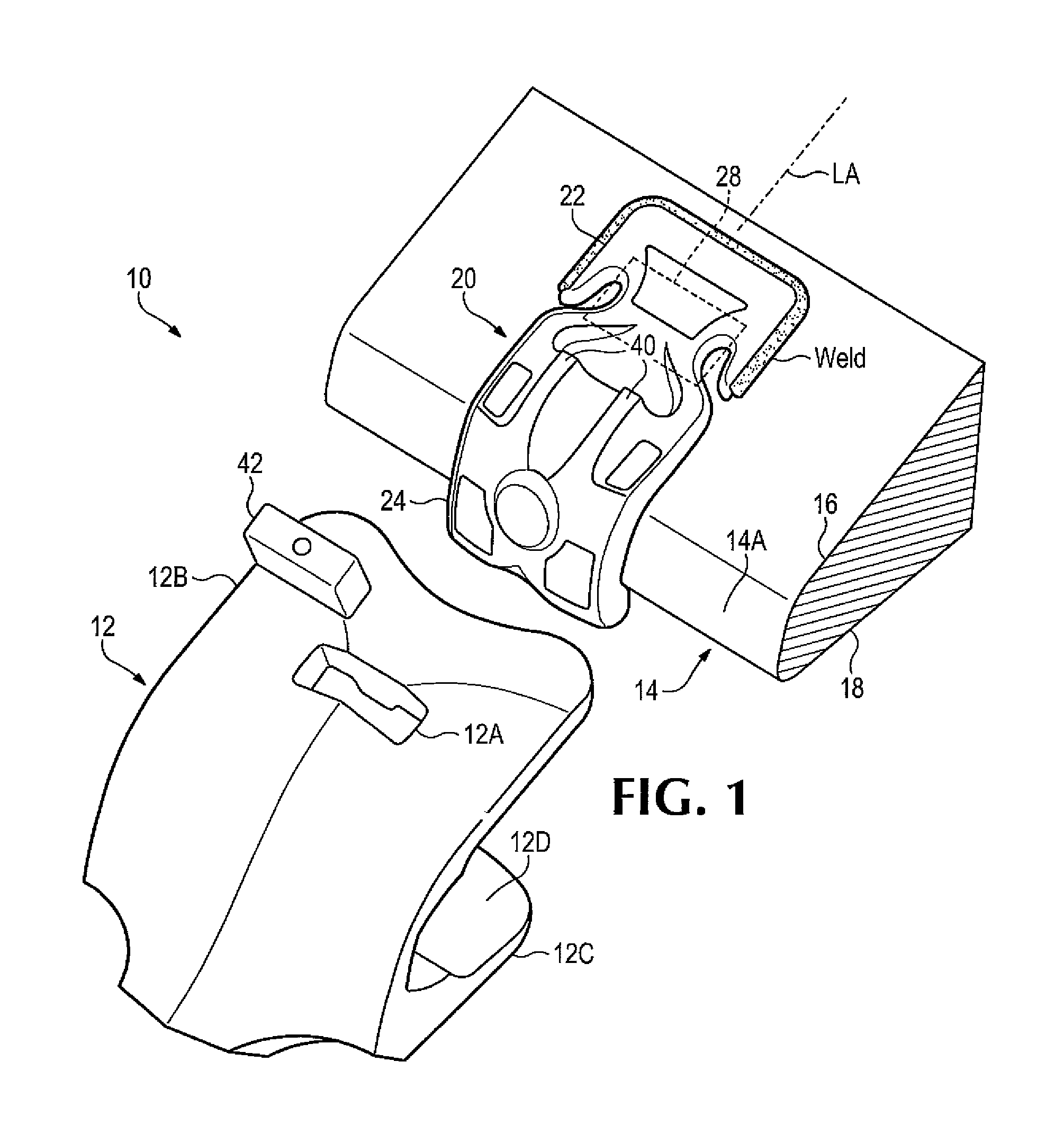
[0031]FIG. 1 is an example of a wear assembly 10 including a wear member 12 being assembled to a base 20. Base 20 is fixed to a lip 14 of excavating equipment with an inside or upper surface 16, an outside or lower surface 18, and a front edge face 14A joining the upper and lower surfaces. Base 20 bears on the front edge face and extends rearward along the upper and lower surfaces. Wear member 12 and base 20 are each considered a wear component of assembly 10.

[0032]Wear member 12 in this illustrated embodiment is a shroud. The wear member includes an opening 12A to receive a retention system or lock 42 to secure the wear member to the base 20. Wear member 12 has bifurcated legs extending backwards so as to straddle lip 14. The upper leg 12B as shown is longer and extends farther rearward than the lower leg 12C, but other arrangements are possible.

[0033]Loads applied to wear me...


PUM

PropertyMeasurementUnit
flexibleaaaaaaaaaa
strengthaaaaaaaaaa
ductilityaaaaaaaaaa

Abstract

A wear assembly with strain relief protects exposed surfaces of excavating equipment such as a bucket lip. Wear components may include a seat where loads are applied, welding flanges flanking the seat on opposite ends of the component welded to the equipment, and strain relief areas between each welding flange and the seat. The strain relief balances stresses from loading in the wear assembly across the weld flange to limit cracking from stress concentrations. Strain relief may include modification of material properties or modification of component configuration to reduce stiffness of the component between the weld flanges and the seat.

Description

CROSS-REFERENCE TO RELATED APPLICATION[0001]The present application claims priority to U.S. Provisional Application No. 61 / 600,437, filed Feb. 17, 2012, which application is incorporated by reference herein in its entirety and made part hereof.FIELD OF THE INVENTION[0002]This invention relates to various wear members and wear assemblies for use with earthmoving equipment.BACKGROUND OF THE INVENTION[0003]Excavating buckets and other earthmoving equipment are subjected to harsh conditions including abrasive materials, extreme loads and cyclic stresses and strains. Various wear members and wear assemblies are attached to lips, other digging edges and surfaces to protect them from wear and erosion. The wear assemblies extending from the digging edges and surfaces experience high internal stresses during operation which can result in failure of the components. The wear assemblies require adequate strength to avoid failure, but also have to incorporate ductility in order to transfer appli...

Claims


Application Information

Patent Timeline
Patent Type & Authority Patents(United States)
IPC IPC(8): E02F9/28
CPCE02F9/2883B28D1/188E02F9/2825
Inventor STANGELAND, KEVIN S.WOOD, CLINTON A.SHREEVE, KATE L.OLLINGER, IV, CHARLES G.
Owner ESCO GRP LLC
Why Eureka
Try Eureka