Busway joint pack with heat sink insert

a busway and insert technology, applied in the direction of butt joining busway, electric cable installation, coupling device connection, etc., can solve the problems of affecting the required size of the busway section and/or the size of the phase-conductors, affecting the overall thermal performance of the busway system, and managing the rise in temperature. , to achieve the effect of reducing the internal temperatur

Active Publication Date: 2015-01-06
SCHNEIDER ELECTRIC USA INC
View PDF20 Cites 10 Cited by
  • Summary
  • Abstract
  • Description
  • Claims
  • Application Information

AI Technical Summary

Benefits of technology

[0005]The present disclosure is directed to providing a busway joint pack with a heat sink insert. The busway joint pack is configured to passively transfer thermal energy or heat from its core to an exterior housing such that the thermal energy is lost or transferred to the surrounding environment, which reduces the internal temperature of the joint pack. The busway joint pack includes a first connector plate and a second connector plate that is spaced from the first connector plate such that the connector plates are configured to engage a pair of phase-conductors of a pair of busway sections. The busway joint pack further includes a first insulator assembly and a second insulator assembly. Each of the insulator assemblies includes a heat sink and two electrically insulating sheets on either major side surface of the heat sinks. The insulator assemblies are positioned adjacent to the connector plates such that the insulating sheets electrically insulate the heat sinks from the connector plates. Side panels are positioned adjacent to the heat sinks and abut end surfaces thereof to aid in transferring heat generated in the busway joint pack to the surrounding environment via the heat sinks and side panels.

Problems solved by technology

A common problem in busway systems is the management of the rise in temperature of the busway system within the busway joint pack.
A rise in temperature within the busway joint pack limits the overall thermal performance of the busway system, which directly affects the required size of the busway sections and / or the size of the phase-conductors therein.
Another problem caused by the rise in temperature at the busway joint pack is a potential degradation of the busway system due to excessive heat, melting, deformation, etc.

Method used


Image

  • Busway joint pack with heat sink insert
  • Busway joint pack with heat sink insert
  • Busway joint pack with heat sink insert

Examples


Embodiment Construction

[0013]Although the invention will be described in connection with certain aspects and / or implementations, it will be understood that the invention is not limited to those particular aspects and / or implementations. On the contrary, the invention is intended to cover all alternatives, modifications, and equivalent arrangements as may be included within the spirit and scope of the invention as defined by the appended claims.

[0014]Words of degree, such as “about”, “substantially”, and the like are used herein in the sense of “at, or nearly at, when given the manufacturing, design, and material tolerances inherent in the stated circumstances” and are used to prevent the unscrupulous infringer from unfairly taking advantage of the invention disclosure where exact or absolute figures and operational or structural relationships are stated as an aid to understanding the invention.

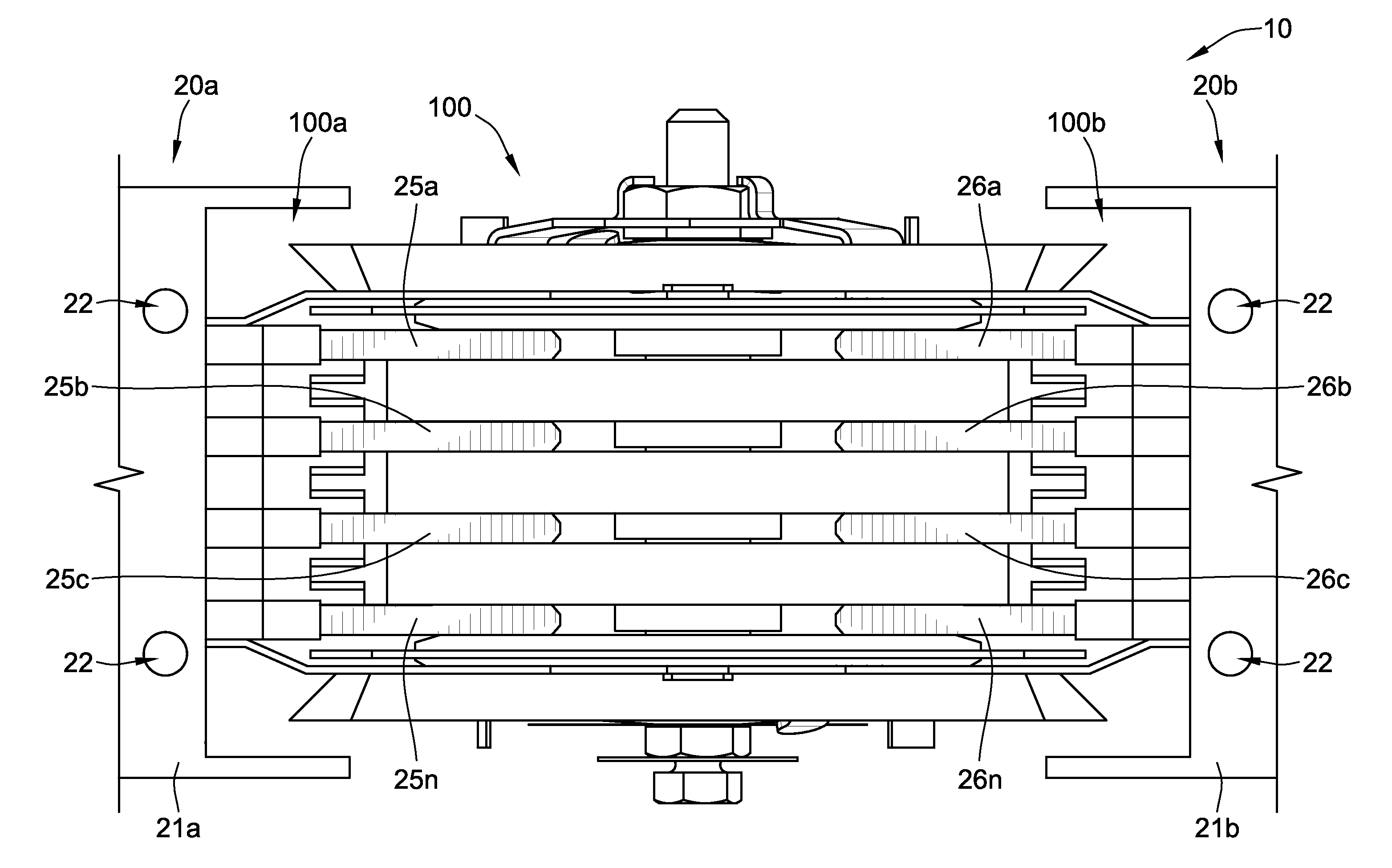
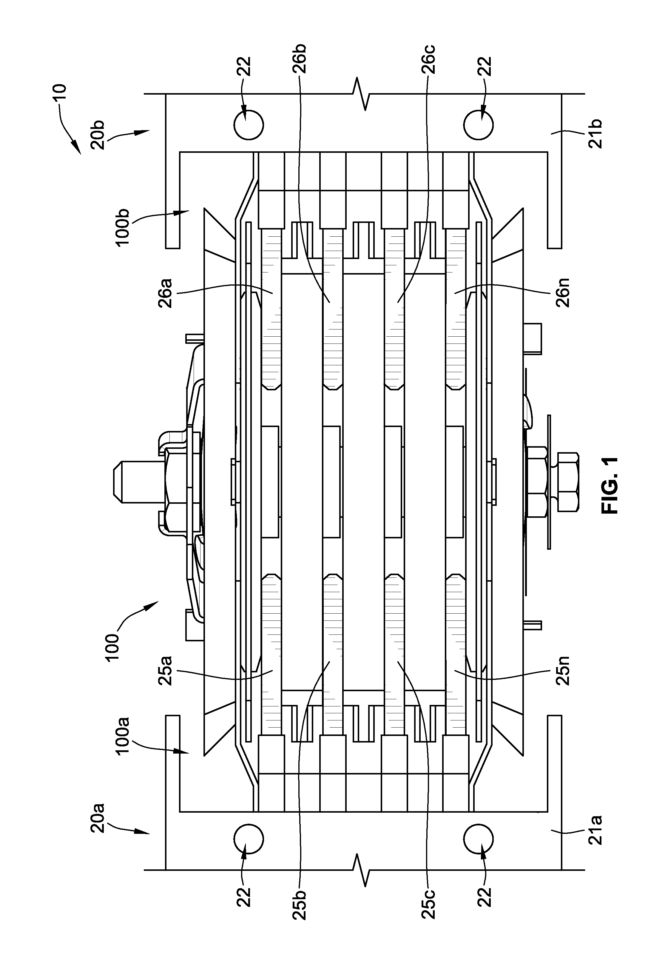
[0015]Referring to FIG. 1, a busway system 10 is shown. The busway system 10 includes a busway joint pack or join...


PUM


Abstract

A busway joint pack includes a first connector plate and a second connector plate that is spaced from the first connector plate such that the connector plates are configured to engage a pair of phase-conductors of a pair of busway sections. The busway joint pack further includes a first insulator assembly and a second insulator assembly. Each of the insulator assemblies includes a heat sink and two electrically insulating sheets on either major side surface of the heat sinks. The insulator assemblies are positioned adjacent to the connector plates such that the insulating sheets electrically insulate the heat sinks from the connector plates. Side panels are positioned adjacent to the heat sinks and abut end surfaces thereof to aid in transferring heat generated in the busway joint pack to the surrounding environment via the heat sinks and side panels.

Description

FIELD OF THE INVENTION[0001]The present invention relates generally to electrical distribution equipment and, more particularly, to busway joint packs with heat sink inserts.BACKGROUND OF THE INVENTION[0002]A busway system typically includes two or more busway sections, one or more busway joint packs (e.g., electrical bus connectors) for connecting two busway sections together, and may include multiple plug-in units. Each busway section includes one or more phase-conductors and a housing. For example, in a three-phase system, the busway section can include three live phase-conductors or three live phase-conductors and one neutral-conductor, depending on the type of system architecture being employed. If required, various plug-in units or electrical components can be directly connected to one or more plug-in connection sites spaced along the busway sections to draw power. Each busway joint pack is used to physically and electrically connect two busway sections or two sets of busway t...

Claims


Application Information

Patent Timeline
Patent Type & Authority Patents(United States)
IPC IPC(8): H01R4/60H01R25/16H02G5/00
CPCH01R25/162H02G5/007
Inventor O'LEARY, TIMOTHY P.PLUMMER, DAVID O.MCCROCKLIN, THOMAS P.
Owner SCHNEIDER ELECTRIC USA INC
Why Eureka
Try Eureka