Backlight module and liquid crystal display device incorporating the same

a backlight module and liquid crystal display technology, applied in non-linear optics, instruments, optics, etc., can solve the problems of not being able to display, lcd panel of an lcd device, and increasing the quality of lcd devices, so as to reduce the internal temperature of the backlight module and effectively dissipate heat. , the effect of improving the luminance efficiency of the light sour

Inactive Publication Date: 2007-08-09
AU OPTRONICS CORP
View PDF10 Cites 13 Cited by
  • Summary
  • Abstract
  • Description
  • Claims
  • Application Information

AI Technical Summary

Benefits of technology

[0009]It is therefore an object of the invention to provide a backlight module and a liquid crystal display device incorporating the same. The design of enabling the heat dissipation element to pass through the bezel and be projected outside the bezel effectively dissipates the heat generated inside the light source of the backlight module, so that the internal temperature of the backlight module is decreased. Thus, the luminance efficiency of the light source is improved, the luminance of the backlight module is enhanced, and operation quality of the liquid crystal display device is maintained.

Problems solved by technology

And further with large amount of input in research and development and the adoption of large-scaled production facilities, the quality of LCD devices continue to increase yet the prices keep falling down.
However, the LCD panel of an LCD device is a not a self-luminous display panel, and can not display without being availed by the light provided by a backlight module.
Besides, the lamp is enclosed inside the backlight module, so the heat generated by the lamp is unable to be dissipated effectively.
Therefore, the luminance efficiency of the lamp tends to deteriorate in a high-temperature work environment.
Thus, the luminance of the backlight module is largely reduced, and the operation quality of the liquid crystal display device is severely affected.
Particularly, when the scale of the liquid crystal display device and the scale of the backlight module are getting larger and larger, the lamp needs to be longer and the starting voltage of the lamp becomes larger and larger.
Consequently, while the temperature inside the backlight module grows higher and higher, the luminance efficiency of the lamp is deteriorated, and the operation quality of the liquid crystal display device is decreased.

Method used


Image

  • Backlight module and liquid crystal display device incorporating the same
  • Backlight module and liquid crystal display device incorporating the same
  • Backlight module and liquid crystal display device incorporating the same

Examples


first embodiment

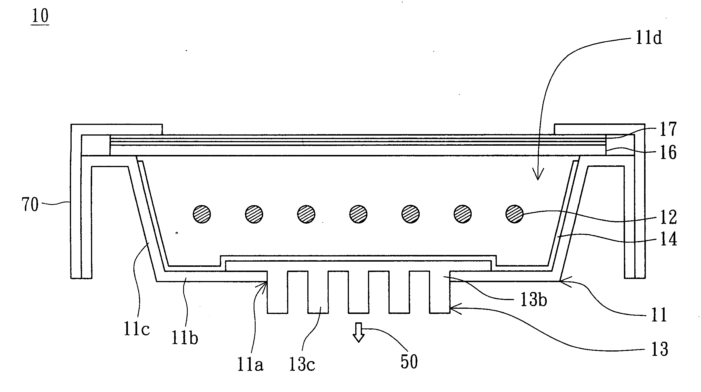
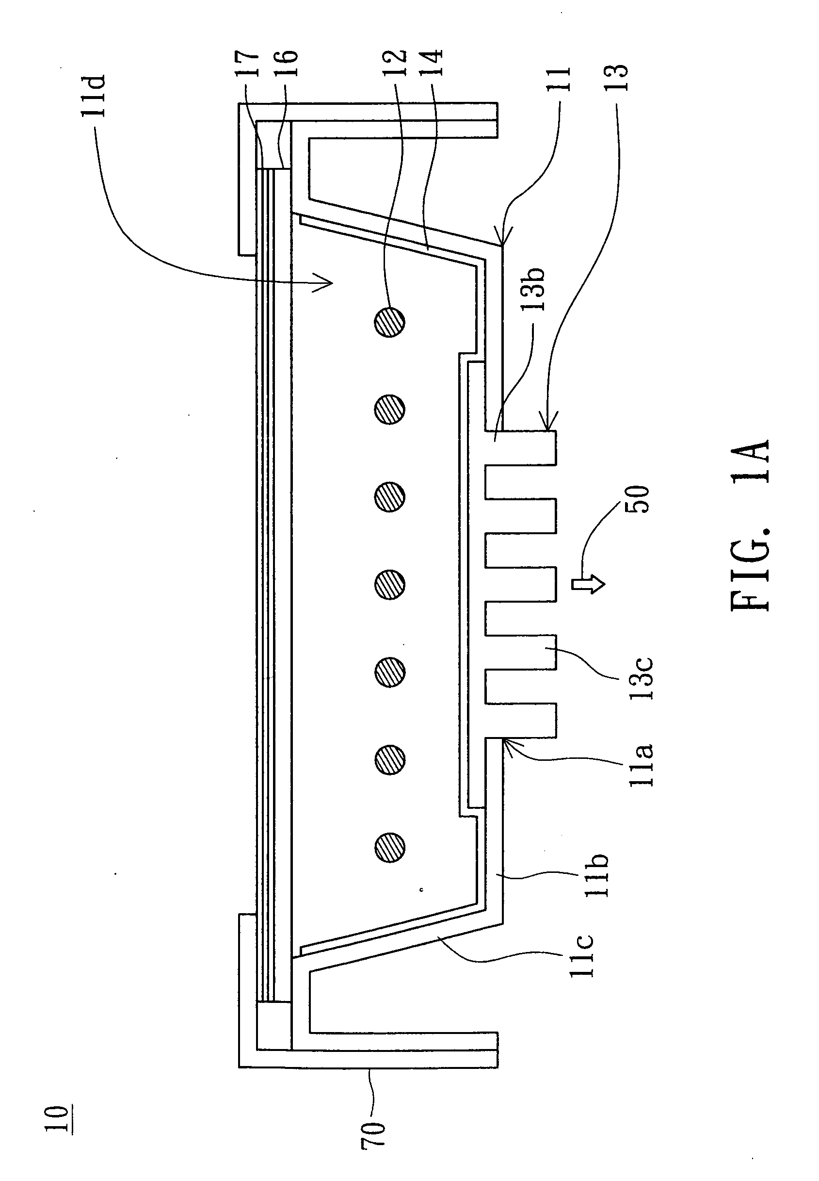
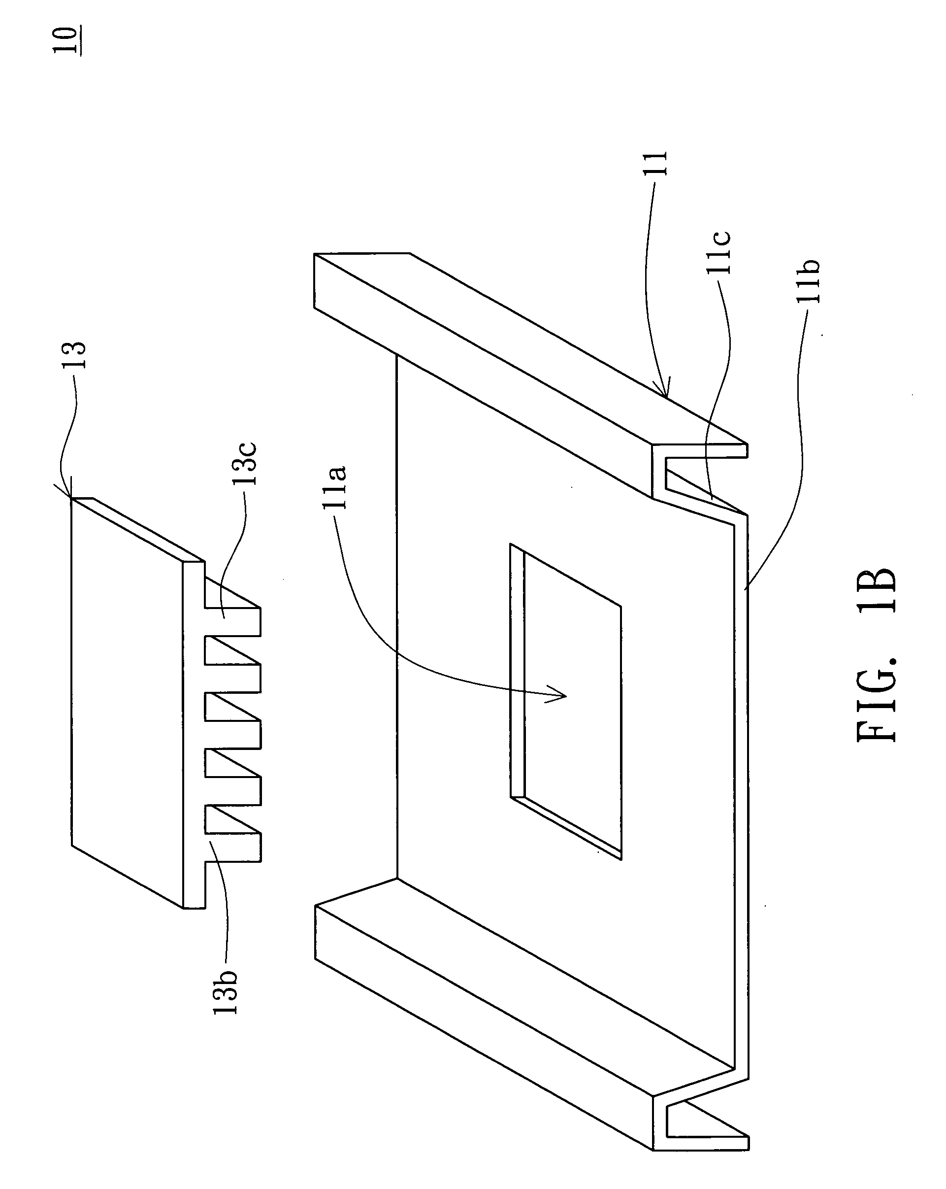
[0023]Please refer to FIG. 1A and FIG. 1B at the same time. FIG. 1A schematically illustrates a backlight module according to a first embodiment of the invention. FIG. 1B illustrates an exploded diagram of a bezel and a heat dissipation element of FIG. 1A. As shown in FIG. 1A and FIG. 1B, the backlight module 10 includes a bezel 11, at least a light source 12, and a heat dissipation element 13. The bezel 11 has at least one opening 1a. The light source 12 is disposed above the bezel 11. The heat generation portion of the light source 12 corresponds to the opening 11a. One end of the heat dissipation element 13 is positioned between the bezel 11 and the light source 12. The other end of the heat dissipation element 13 has a protrusion portion 13b. The protrusion portion 13b is inserted into the opening 11a and projected outside the bezel 11. The lateral surface of the protrusion portion 13b is abutted against the inner wall of the opening 11a for enabling the heat dissipation element...

second embodiment

[0032]Please refer to FIG. 2A and FIG. 2B at the same time. FIG. 2A schematically illustrates a backlight module according to a second embodiment of the invention. FIG. 2B illustrates an exploded diagram of a bezel and a heat dissipation element of FIG. 2A. The backlight module 10a of the present embodiment of the invention differs with the backlight module 10 of the first embodiment in the bezel 11e. The bezel 11e of the present embodiment of the invention differs with the bezel 11 of the first embodiment in the bottom plate 11f. The bottom plate 11f of the present embodiment of the invention differs with the bottom plate 11b of the first embodiment in a number of openings 11g positioned opposite to the fins 13c. As for other similar elements, the same reference labels are used and their connections are not repeated here.

[0033]As shown in FIG. 2A and FIG. 2B, each fin 13c is inserted into its corresponding opening 11g and projected outside the bottom plate 11f of the bezel 11e. The...

third embodiment

[0034]Referring to FIG. 3A and FIG. 3B at the same time. FIG. 3A schematically illustrates a backlight module according to a third embodiment of the invention. FIG. 3B illustrates an exploded diagram of a bezel and a heat dissipation element of FIG. 3A. The backlight module 20 of the present embodiment of the invention differs with the backlight module 10 of the first embodiment in the bezel 21 and the reflector 24. As for other similar elements, the same reference labels are used and their connections are not repeated here.

[0035]As shown in FIG. 3A and FIG. 3B, the bezel 21 has a bottom plate 21b and a side plate 21c connected to the bottom plate 21b. An accommodation space 21d is defined by the bottom plate 21b and the side plate 21c. The light source 12 is disposed in the accommodation space 21d. The bottom plate 21b has a recess 21a. The bottom of the recess 21a has an opening 11a. One end of the heat dissipation element 13 is positioned in recess 21a. The protrusion portion 13b...


PUM

PropertyMeasurementUnit
temperatureaaaaaaaaaa
heataaaaaaaaaa
metallicaaaaaaaaaa

Abstract

A backlight module and a liquid crystal display device incorporating the same are provided. The backlight module includes a bezel, a light source and a heat dissipation element. The bezel has an opening. The light source is disposed on the bezel. The heat generation portion of the light source corresponds to the opening. One end of the heat dissipation element is positioned between the bezel and the light source. The other end of the heat dissipation element has a protrusion portion which is inserted into the opening and projected outside the bezel. The lateral surface of the protrusion portion is abutted against the inner wall of the opening.

Description

[0001]This application claims the benefit of Taiwan Patent Application Serial No. 95104403, filed Feb. 9, 2006, the subject matter of which is incorporated herein by reference.BACKGROUND OF THE INVENTION[0002]1. Field of the Invention[0003]The invention relates in general to a backlight module and a liquid crystal display device incorporating the same, and more particularly to a backlight module, which has a heat dissipation element passing through and projected outside the bezel, and a liquid crystal display device incorporating the same.[0004]2. Description of the Related Art[0005]Along with the advance in the manufacturing technology of liquid crystal display (LCD) device devices and further due to the features of slimness, lightweight, low energy consumption and no radiation, LCD devices have been widely applied in various electronic products such as personal digital assistant (PDA), notebook computer, digital camera, digital video recorder, mobile phone, computer monitor, and l...

Claims


Application Information

Patent Timeline
Patent Type & Authority Applications(United States)
IPC IPC(8): G02F1/1335
CPCG02F1/133604G02F2001/133628G02F1/133608G02F1/133628
Inventor LIN, CHUN-YENSZUTU, YING
Owner AU OPTRONICS CORP
Why Eureka
Try Eureka