Faceted folded-optic collimator

a collimator and faceted technology, applied in the field of faceted foldedoptic collimators, can solve the problems of serious disadvantage and inability to be desirable in some applications, and achieve the effect of wide angular output pattern and no longer affecting the uniformity of output pattern

Inactive Publication Date: 2015-01-13
LIGHT ENGINE
View PDF11 Cites 0 Cited by
  • Summary
  • Abstract
  • Description
  • Claims
  • Application Information

AI Technical Summary

Benefits of technology

[0004]The present invention solves the practical issues presented by traditional high efficiency folded optics, by providing an optical architecture and method of design where the resulting optic (in combination with a solid state light source) has a wide angular output pattern and mixes the light output in such a way that the structure of the source no longer influences the uniformity of the output pattern.
[0005]The present invention addresses the aforementioned problem by adding specially designed peening features to optical surfaces of one embodiment in U.S. Pat. No. 6,896,381 (“patent '381”). The new optic increases the output angle and mixes said output light compared to the original one so that the structure (mechanical or color) of the source is no longer visible in the output pattern. The peening process consists of adding at least one peening feature (e.g., a small “bump” or a plurality of “bumps” (as discussed below, such “bump” can have the same or differing characteristics relative to another “bump”) to the two of the surfaces of embodiment shown in FIG. 17 of patent '381. Also some changes are made to the geometry of the surfaces of FIG. 17 of patent '381 to improve light mixing. In embodiments of the present invention, surface 323 in FIG. 17 of patent '381 can be replaced by a conical surface. In one embodiment in the present invention convex surface 322 of patent '381 is replaced with a planar surface and interior surface 329 is replaced with a peened planar surface (feature 701 of FIG. 7). In a preferred embodiment in the present invention surface 322 of patent '381 is left convex and interior surface 329 is replaced with a peened planar surface.

Problems solved by technology

However, such prior art optics work best for narrow exit angles, which may not be desirable in some applications.
Also, when used with light sources that have color separation or non uniform luminance (as nearly all LED light sources), these optics may create a pattern that mimics the color separation of the source or create artifacts that reflect the form or placement of the chip or chips.
This may be a serious disadvantage in some applications in which a uniform color pattern or intensity distribution is necessary.

Method used


Image

  • Faceted folded-optic collimator
  • Faceted folded-optic collimator
  • Faceted folded-optic collimator

Examples


Embodiment Construction

[0030]A better understanding of various features and advantages of the present invention will be obtained by reference to the following detailed description of embodiments of the present invention and accompanying drawings, which set forth illustrative embodiments in which the principles of the invention are utilized.

[0031]We will first start with the background information needed to design the peened features.

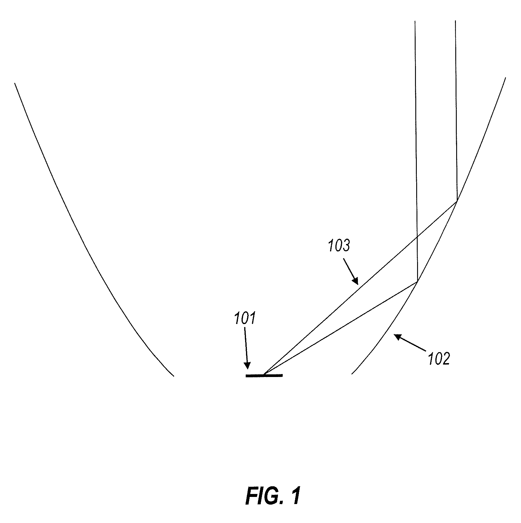
[0032]FIG. 1 shows a light source 101 whose light is collimated by a reflective surface 102. Rays 103 coming from the source are reflected and emitted vertically.

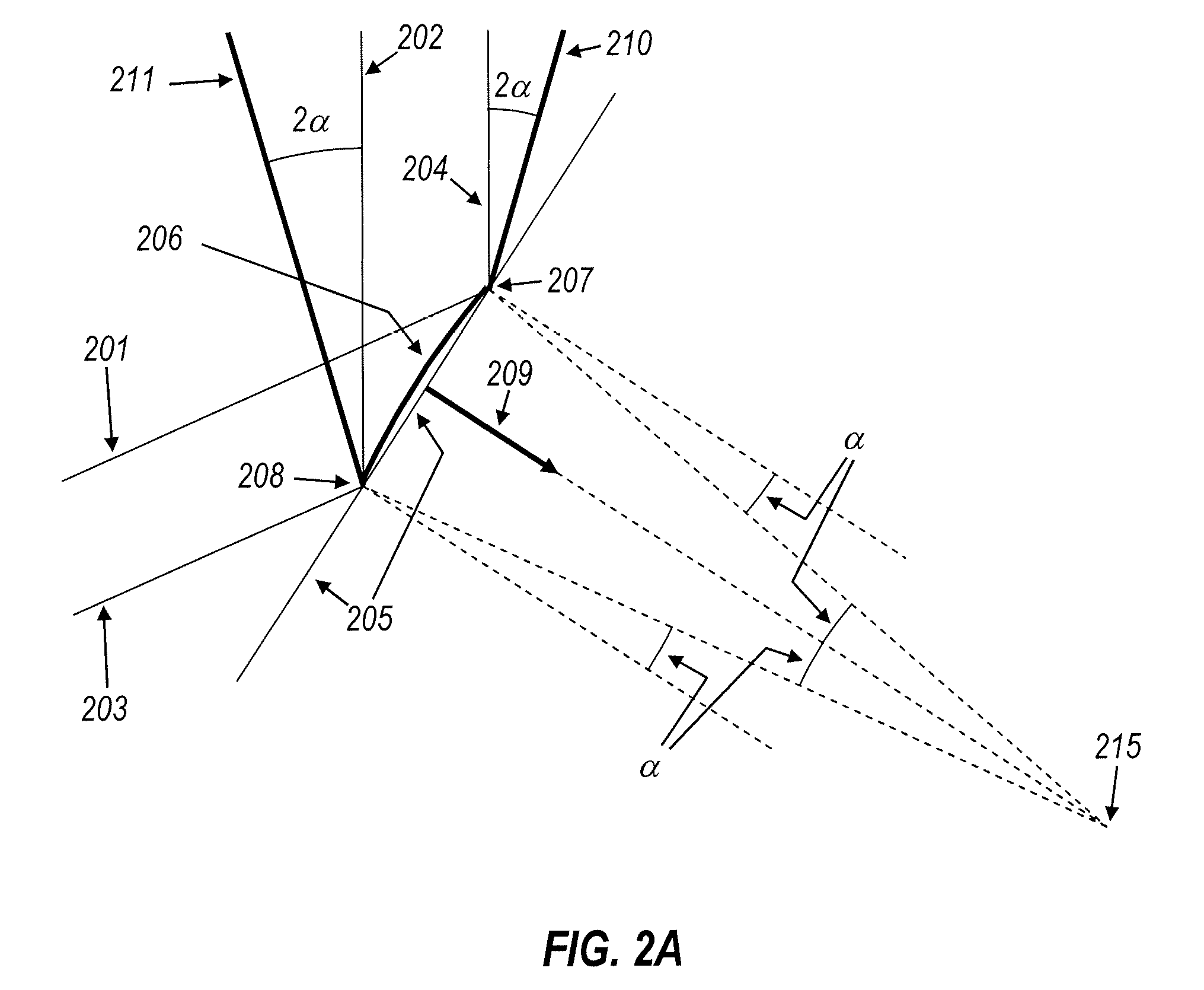
[0033]FIG. 2A shows a detail of a collimating optic similar to that in FIG. 1. Light rays 201 and 203 coming from the light source are reflected upwards as rays 202 and 204 by reflective surface 205. Reflective surface 205 is part of that generic collimator optic similar, for example, to that in FIG. 1. Rays 202 and 204 are essentially parallel and the light output is highly collimated.

[0034]Spreading of the output pa...


PUM


Abstract

A folded circularly symmetric illumination optic comprising a first light transfer mode having a first central refractive surface and a second central refractive surface, wherein one of the first and second central refractive surfaces has at least one peened feature; a second light transfer mode having a first refractive surface, a first TIR surface, a second TIR surface and a second refractive surface; a third light transfer mode having a first refractive surface, a first TIR surface and a second refractive surface, wherein the first TIR surface has at least one peening feature, and wherein the second refractive surface is conical; wherein the first TIR surface and second refractive surface of the second light transfer mode is coincident at least one point, wherein the second refractive surface of the third light transfer mode is coincident with the first TIR surface and second refractive surface of the second light transfer mode.

Description

CROSS REFERENCE TO RELATED APPLICATION[0001]This application claims benefit under 35 U.S.C. §119(e) to U.S. Ser. Nos. 61 / 495,094, filed Jun. 9, 2011, and 61 / 499,250, filed Jun. 21, 2011, which are both hereby incorporated by reference in this application.[0002]Throughout this application, several references and patents are referenced herein. Disclosure of these references and patents in their entirety is hereby incorporated by reference in this application.BACKGROUND OF THE INVENTION[0003]High efficiency etendue limited folded optics have been known for some years, such as U.S. Pat. Nos. 6,639,733, 6,896,381, 7,152,985, 7,181,378, all of which have several inventors in common with the present application. However, such prior art optics work best for narrow exit angles, which may not be desirable in some applications. Also, when used with light sources that have color separation or non uniform luminance (as nearly all LED light sources), these optics may create a pattern that mimics ...

Claims


Application Information

Patent Timeline
Patent Type & Authority Patents(United States)
IPC IPC(8): F21V7/00G02B19/00
CPCG02B19/0028G02B19/0061
Inventor DROSS, OLIVERMOHENDANO, RUBENCHAVES, JULIO C.MUNOZ, FERNANDOMINANO, JUAN CARLOSFALICOFF, WAQIDI
Owner LIGHT ENGINE
Why Eureka
Try Eureka