Resin injection molding method
a technology of resin injection and molding method, applied in the direction of coatings, etc., can solve the problems of disfigurement of the shaped object, and achieve the effect of suppressing the appearance, sufficient fluidity, and suppressing the appearan
- Summary
- Abstract
- Description
- Claims
- Application Information
AI Technical Summary
Benefits of technology
Problems solved by technology
Method used
Image
Examples
example 1
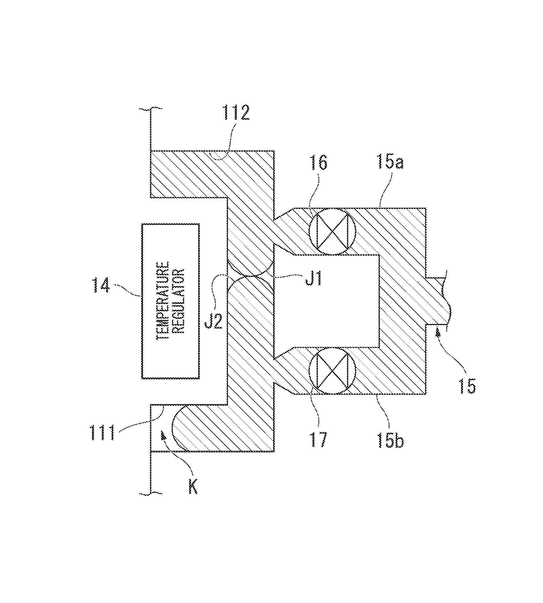
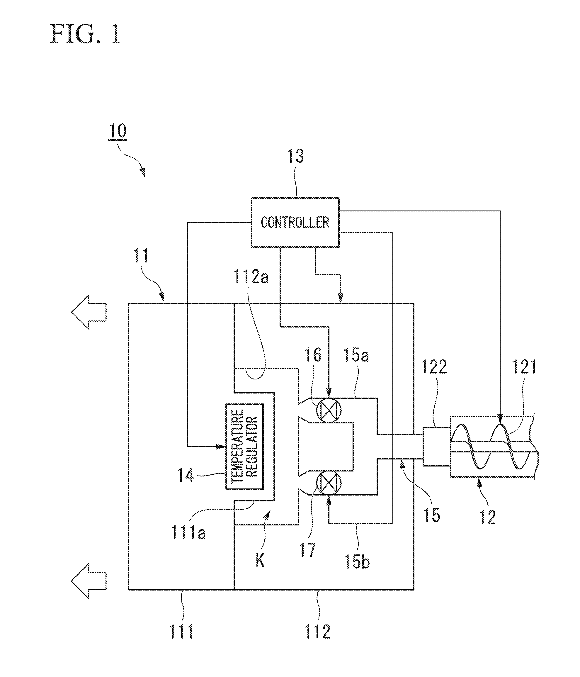
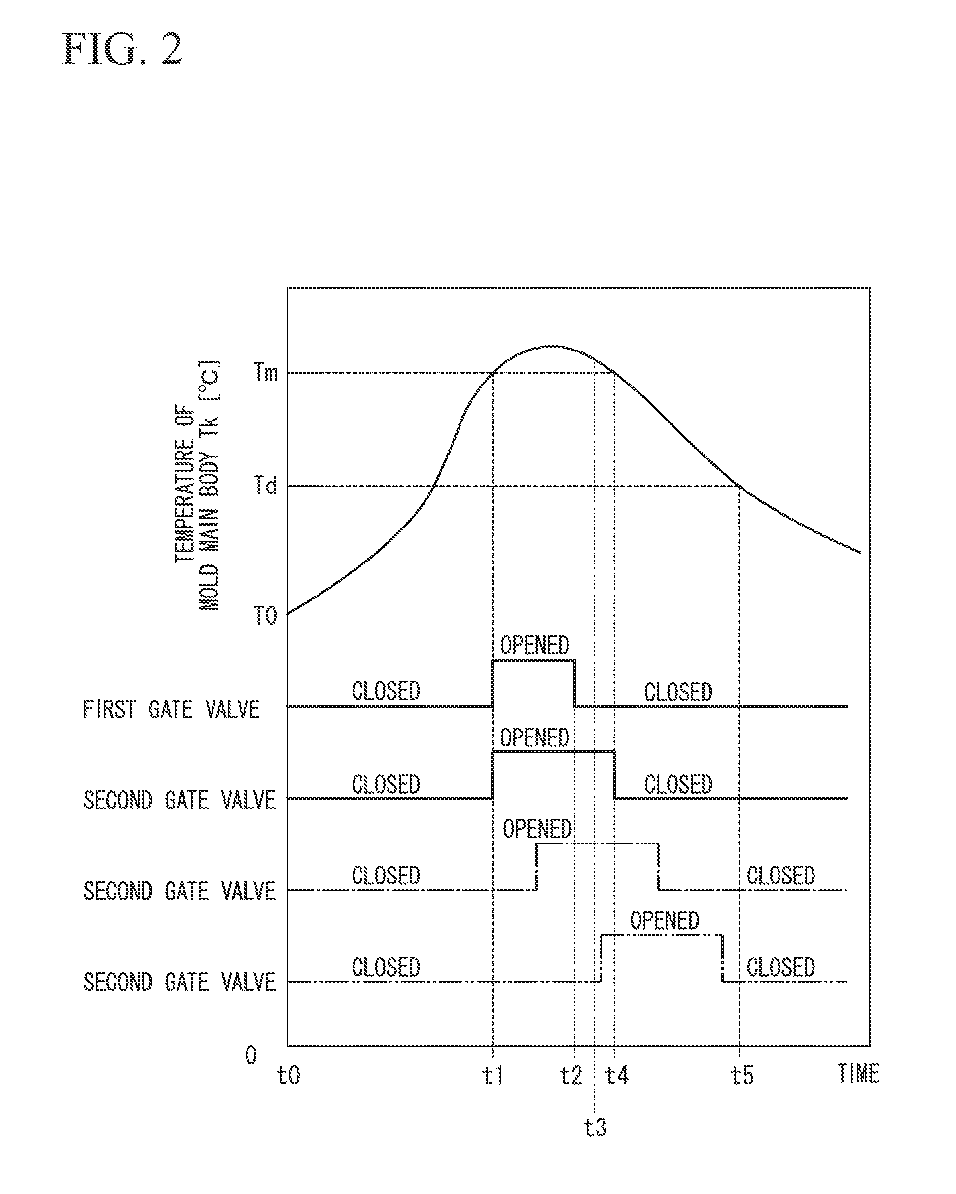
[0049]The inventors have discovered a technique to suppress the appearance of a weld which is a border of the converged portion by conducting an actual molding trial under the procedures shown below. Of a pair of paths where injected resins converge with each other, a difference is given in between the time at which the first path is closed and the time at which the second path is closed. In addition, the resin, which is injected from a path which is closed at an earlier time, that is, the resin to be submerged, is solidified at a crystallinity greater than or equal to a predetermined crystallinity. Further, so that the effect of the present invention is substantially effective (in order to suppress the appearance of a weld to a degree that is acceptable as a final product on the market), the inventors have found that the resin to be submerged needs to be 20% or greater in crystallinity.
[0050]Molding machine: Injection molding machine 450 ME2-50 (screw diameter (φ70) manufactured by...
example 2
[0071]The inventors have discovered a technique to suppress the appearance of a weld which is a border of the converged portion by conducting an actual molding trial under the procedures shown below. Of a pair of paths where injected resins converge with each other, a difference is given between the time at which maintaining a resin inside the cavity at pressure is completed at the first path and the time at which maintaining a resin inside the cavity at pressure is completed at the second path. In addition, the resin, which is injected from the path at which maintaining the resin inside the cavity at pressure is completed at an earlier time, that is, the resin to be submerged, is solidified at a crystallinity greater than or equal to a predetermined crystallinity. Further, in the present example as well, so that the effect of the present invention is substantially effective (the appearance of the weld is suppressed to a degree that is acceptable as a final product on the market), t...
example 3
[0082]The inventors have discovered a technique to suppress the appearance of a weld which is a border of the converged portion by conducting an actual molding trial under the procedures shown below. Of a pair of paths where injected resins converge with each other, a difference is given between a pressure value at which a resin is maintained at pressure at the first path and a pressure value at which a resin is maintained at pressure at the second path. In addition, the resin, which is injected from the first path where the resin is maintained in lower pressure value, that is, the resin to be submerged, is solidified at a crystallinity greater than or equal to a predetermined crystallinity. Further, in the present example as well, so that the effect of the present invention is substantially effective (the appearance of the weld is suppressed to a degree that is acceptable as a final product on the market), the inventors have found that the resin to be submerged needs to be 20% or g...
PUM
| Property | Measurement | Unit |
|---|---|---|
| angle | aaaaa | aaaaa |
| angle | aaaaa | aaaaa |
| angle | aaaaa | aaaaa |
Abstract
Description
Claims
Application Information
 - R&D
- Intellectual Property
- Life Sciences
- Materials
- Tech Scout
- Unparalleled Data Quality
- Higher Quality Content
- 60% Fewer Hallucinations
Browse by: Latest US Patents, China's latest patents, Technical Efficacy Thesaurus, Application Domain, Technology Topic, Popular Technical Reports.
© 2025 PatSnap. All rights reserved.Legal|Privacy policy|Modern Slavery Act Transparency Statement|Sitemap|About US| Contact US: help@patsnap.com


