
Sealant material composition

a technology of sealing agent and composition, applied in the field of sealing agent material composition, can solve the problems of insufficient sealing agent, difficult sealing agent flow into, and insufficient sealing properties, so as to achieve good sealing properties, suppress the flow of sealing agent due to traveling, and ensure good sealing properties

Pending Publication Date: 2022-10-13
YOKOHAMA RUBBER CO LTD
View PDF6 Cites 0 Cited by
  • Summary
  • Abstract
  • Description
  • Claims
  • Application Information

AI Technical Summary

Benefits of technology

The present invention provides a sealant material composition for pneumatic tires that has excellent physical properties and can effectively seal while also being fluid enough to allow for good processability. The composition includes a blend of chlorinated butyl rubber and another halogenated rubber, which, when used together, helps to achieve the desired balance of elasticity and viscosity for good sealing properties and flow control during travel. The composition also includes a combination of a crosslinking agent, an organic peroxide, and a rubber component containing another halogenated butyl rubber, which helps to provide consistent physical properties and viscosity across the sealant layer after vulcanization. Additionally, the composition can further include a crosslinking aid, such as a thiazole-based compound or a thiuram-based compound, to increase the vulcanization rate and enhance productivity. The pneumatic tire including this sealant layer has good sealing properties and suppresses fluidity during travel and use.

Problems solved by technology

In the self-sealing type pneumatic tire described above, when the viscosity of the sealant is lower, since the sealant easily flows into the through-hole, improvement of sealing properties can be expected; however, in a case where the sealant flows toward a tire center side due to the effects of heat and centrifugal force applied during travel and, as a result, the through-hole deviates from a tire center region, there is concern that the sealant becomes insufficient and sealing properties cannot be obtained sufficiently.
On the other hand, when the viscosity of the sealant is high, a flow of the sealant described above can be prevented, but the sealant becomes difficult to flow into the through-hole, and there is concern that the sealing properties decrease.
Thus, it is difficult to ensure good sealing properties while suppressing flow of the sealant due to traveling, and there is a demand for a measure for providing these performances in a well-balanced, compatible manner by improving the physical properties of the sealant material composition that forms the sealant layer.

Method used


Image

  • Sealant material composition

Examples


examples

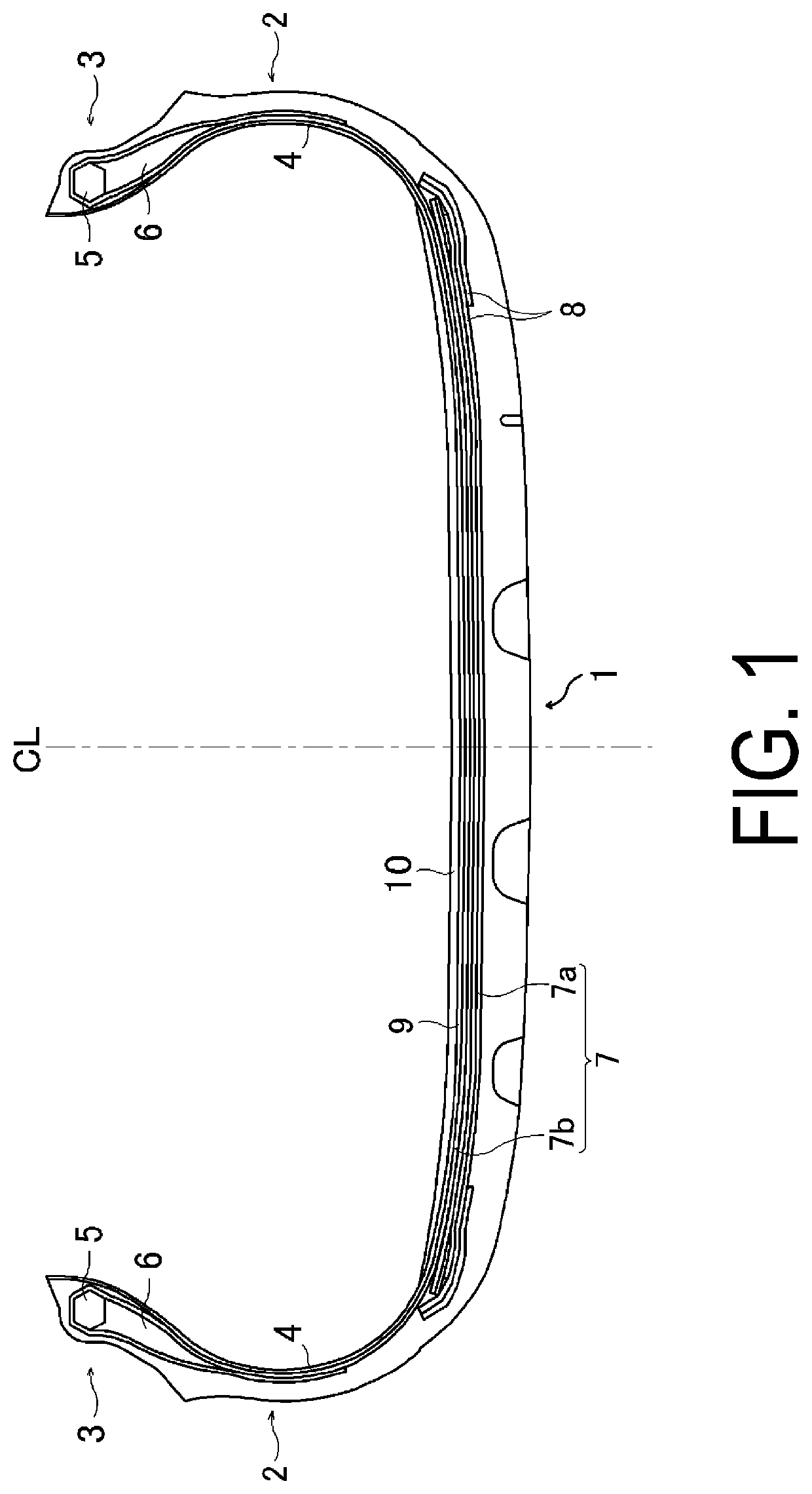
[0039]Tires according to Comparative Examples 1 to 7 and Examples 1 to 36 were manufactured. The tires have a tire size of 255 / 40R20, include the basic structure illustrated in FIG. 1, and include a sealant layer formed of a sealant on an inner side in a tire radial direction of an innerliner layer in a tread portion. The composition of the sealant material composition constituting the sealant layer was set as listed in Tables 1 to 4.

[0040]For these test tires, sealing properties (initial performance and after heat degradation acceleration treatment) and fluidity of the sealant were evaluated by the following test methods, and the results are shown in Tables 1 to 4.

Sealing Properties (Initial Performance)

[0041]The test tires were assembled on wheels having a rim size of 20×9J and mounted on a test vehicle, with an initial air pressure of 250 kPa and a load of 8.5 kN, a 4 mm-diameter nail was driven into the tread portion, and then the test tire was left to stand for one hour in a st...


PUM

PropertyMeasurementUnit
mass %aaaaaaaaaa
one-minute half-life temperatureaaaaaaaaaa
inclination angleaaaaaaaaaa

Abstract

Provided is a sealant material composition that makes it possible to ensure good sealing properties and to suppress sealant flow due to traveling. As a sealant material composition forming a sealant layer disposed on an inner surface of a pneumatic tire, a sealant material composition comprising from 1 part by mass to 40 parts by mass of an organic peroxide and from 0.1 parts by mass to 40 parts by mass of a crosslinking agent, being blended, per 100 parts by mass of a rubber component containing a chlorinated butyl rubber, is used.

Description

TECHNICAL FIELD[0001]The present invention relates to a sealant material composition forming a sealant layer of a self-sealing type pneumatic tire including the sealant layer in a tire inner surface.BACKGROUND ART[0002]In a known pneumatic tire, a sealant layer is provided in an inner side in a tire radial direction of an innerliner layer in a tread portion (for example, see Patent Document 1). In such a pneumatic tire, when a foreign substance such as a nail or the like penetrates into the tread portion, the sealant flows into the through hole, which makes it possible to suppress reduction in air pressure and to maintain travel.[0003]In the self-sealing type pneumatic tire described above, when the viscosity of the sealant is lower, since the sealant easily flows into the through-hole, improvement of sealing properties can be expected; however, in a case where the sealant flows toward a tire center side due to the effects of heat and centrifugal force applied during travel and, as ...

Claims


Application Information

Patent Timeline
Patent Type & Authority Applications(United States)
IPC IPC(8): C09K3/10B60C5/16C08L23/28
CPCC09K3/1006B60C5/16C08L23/283C08L23/22C08L91/06C09K3/10C08K5/14C08K3/06C08K5/36C08K5/40C08L91/00C08L23/28B29C73/163
Inventor TAKAHASHI, KIYOHITO
Owner YOKOHAMA RUBBER CO LTD
Learn More