Miniature surface mount technology electromagnetic interference shielding device

a shielding device and miniature surface technology, applied in the direction of coupling device connections, instruments, contact material of connection, etc., can solve the problems of high material cost, inconsistent assembly process, and continued material obsolescen

Active Publication Date: 2015-01-13
ROCKWELL COLLINS INC
View PDF16 Cites 12 Cited by
  • Summary
  • Abstract
  • Description
  • Claims
  • Application Information

AI Technical Summary

Problems solved by technology

Currently available electromagnetic interference (EMI) shielding solutions may exhibit one or more of the following characteristics: high material cost; inconsistent assembly processes; significant compression set; inconsistent performance following mu...

Method used


Image

  • Miniature surface mount technology electromagnetic interference shielding device
  • Miniature surface mount technology electromagnetic interference shielding device
  • Miniature surface mount technology electromagnetic interference shielding device

Examples


Embodiment Construction

[0017]Reference will now be made in detail to the presently preferred embodiments of the invention, examples of which are illustrated in the accompanying drawings.

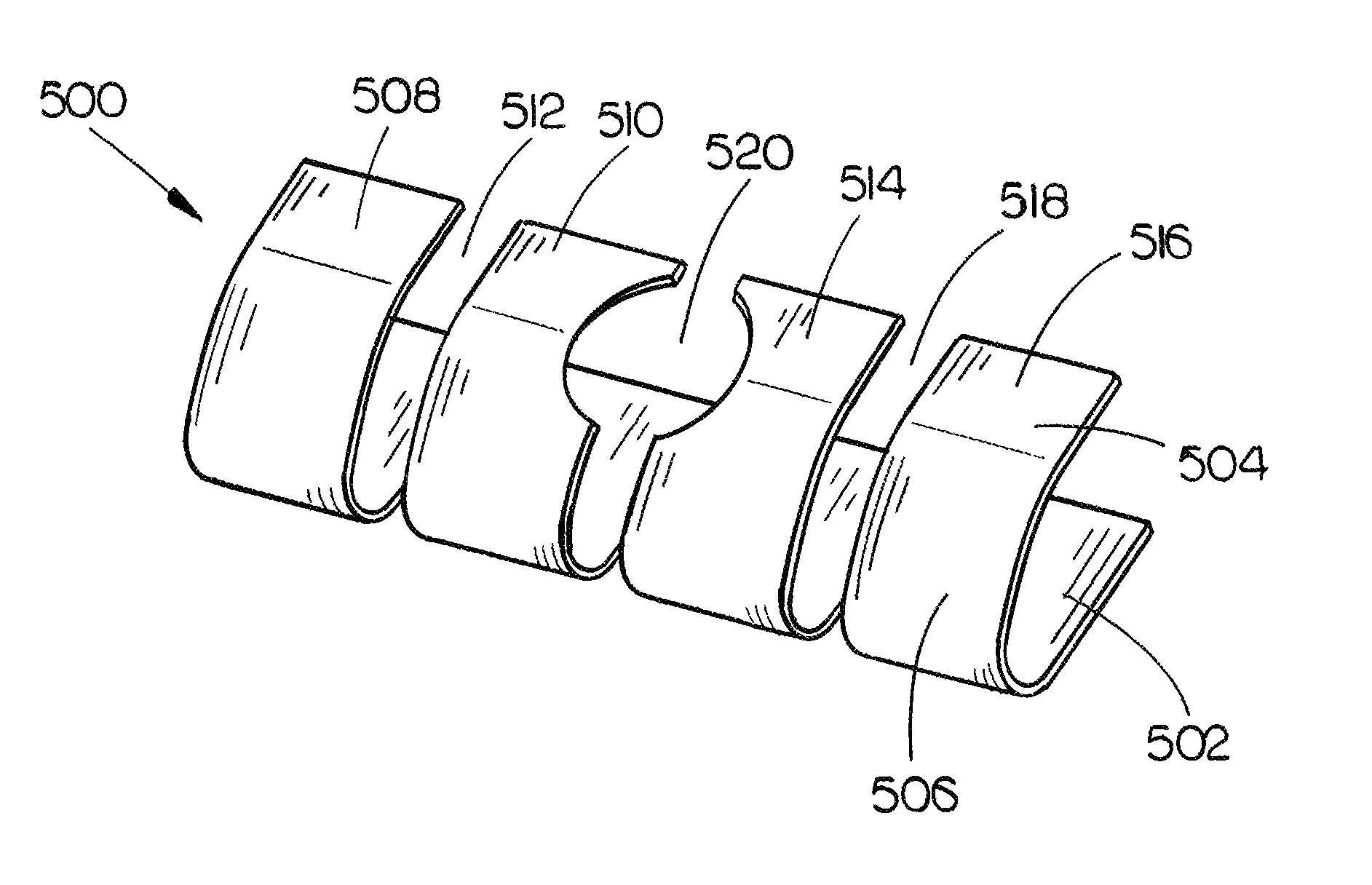
[0018]Referring to FIG. 1, a shielding device in accordance with an exemplary embodiment of the present invention is shown. For example, the shielding device 100 may be an Electromagnetic Interference (EMI) shielding device. In exemplary embodiments of the present invention, the shielding device 100 may be a Surface Mounted Component (SMC), which may be configured for being mounted directly onto a surface. For instance, the SMC 100 may be configured for being mounted directly onto a Printed Circuit Board (PCB) surface via Surface Mount Technology (SMT). In further embodiments of the present invention, said SMC 100 and PCB may collectively form and / or may be included as part of a Surface Mount Device (SMD). For example, the SMD may be an electronic circuit and / or electronic device.

[0019]In exemplary embodiments of the prese...


PUM


Abstract

The present invention is directed to an electromagnetic interference (EMI) shielding device. The EMI shielding device may be formed of a material (ex.—Beryllium Copper) having a thickness which allows the shielding device to provide a desired range of compression. Further, the EMI shielding device may be constructed for accommodating tolerances and compression forces which may be encountered in various implementation environments. Further, the EMI shielding device may be sized and shaped for promoting compatibility of the EMI shielding device with Surface Mount Technology (SMT) processes.

Description

FIELD OF THE INVENTION[0001]The present invention relates to the field of low cost avionics, and more particularly, to a miniature surface mount technology (SMT) electromagnetic interference (EMI) shielding device.BACKGROUND OF THE INVENTION[0002]Currently available electromagnetic interference (EMI) shielding solutions may exhibit one or more of the following characteristics: high material cost; inconsistent assembly processes; significant compression set; inconsistent performance following multiple open / closure cycles; continued material obsolescence; poor suitability for high temperature performance; galvanic incompatibility; large footprint; require complex cover geometry; require large compression force; and / or insufficient compression range.[0003]Thus, it would be desirable to provide an EMI shielding solution which overcomes one or more of the above-referenced negative characteristics associated with currently available solutions.SUMMARY OF THE INVENTION[0004]Accordingly an e...

Claims


Application Information

Patent Timeline
IPC IPC(8): H05K9/00H01R4/66H01R13/648
CPCG06F1/182H01R13/6581H05K9/0016
Inventor KRAMER, JOHN F.STRENECKY, JOSEPH M.GOULD, NATHANIEL T.
Owner ROCKWELL COLLINS INC
Why Eureka
Try Eureka