Printing apparatus

a printing apparatus and printing technology, applied in the direction of printing, other printing apparatus, power drive mechanisms, etc., can solve the problems of one-sided control mechanisms for applying pressure, difficult to vary the pressure setting to account for different qualities and/or different, and restricted typical applications of printers of this typ

Active Publication Date: 2015-01-20
DOMINO PRINTING SCIENCES
View PDF14 Cites 17 Cited by
  • Summary
  • Abstract
  • Description
  • Claims
  • Application Information

AI Technical Summary

Benefits of technology

[0039]The invention has a number of advantages over the state of the art. If the substrate is compressible then the Hall effect sensor will register an increment at a reduced slope to that stored in its look-up table. By controlling the difference in sensor readings, the printer thus compensates for the compressibility of the substrate, which may change from print to print. If the distance of the substrate from the printer changes during a print, due for example to poor alignment of the substrate to the print head, then the print head will be retracted or extended in line with the feedback received from the sensor, to maintain good print quality.

Problems solved by technology

This method has the drawback that it is difficult to vary the pressure setting to account for different qualities and / or different thicknesses of substrate to be printed.
Another problem with prior art forms of apparatus is that the control mechanisms for applying pressure are one-sided in that they compensate for a substrate becoming thinner by stepping the head is down.
As a consequence, typical applications for printers of this type are restricted to substrates whose thickness is well controlled, and largely flat.

Method used


Image

  • Printing apparatus
  • Printing apparatus
  • Printing apparatus

Examples


Embodiment Construction

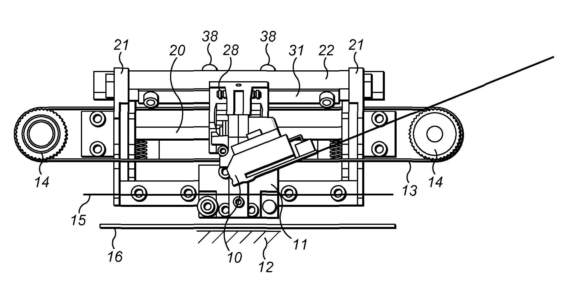
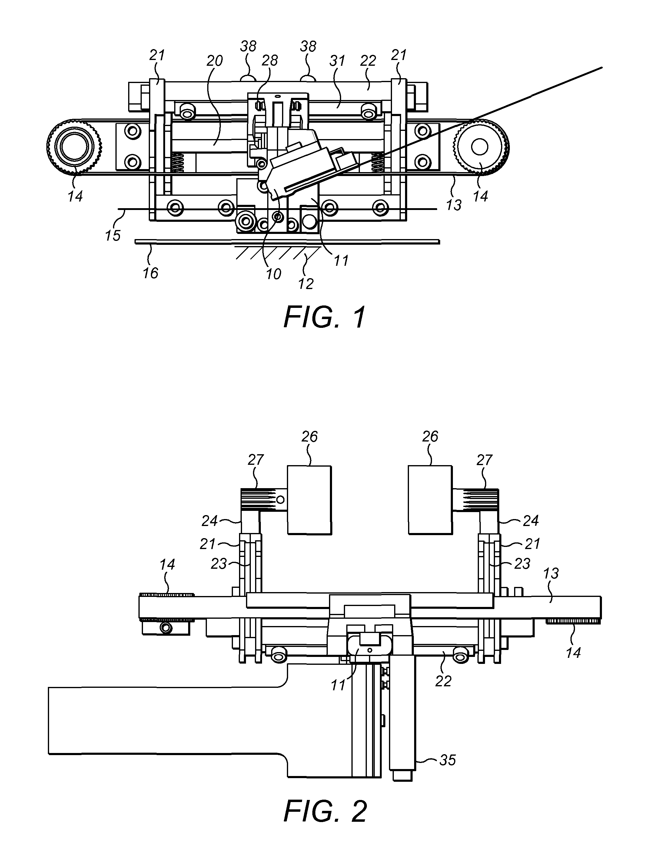
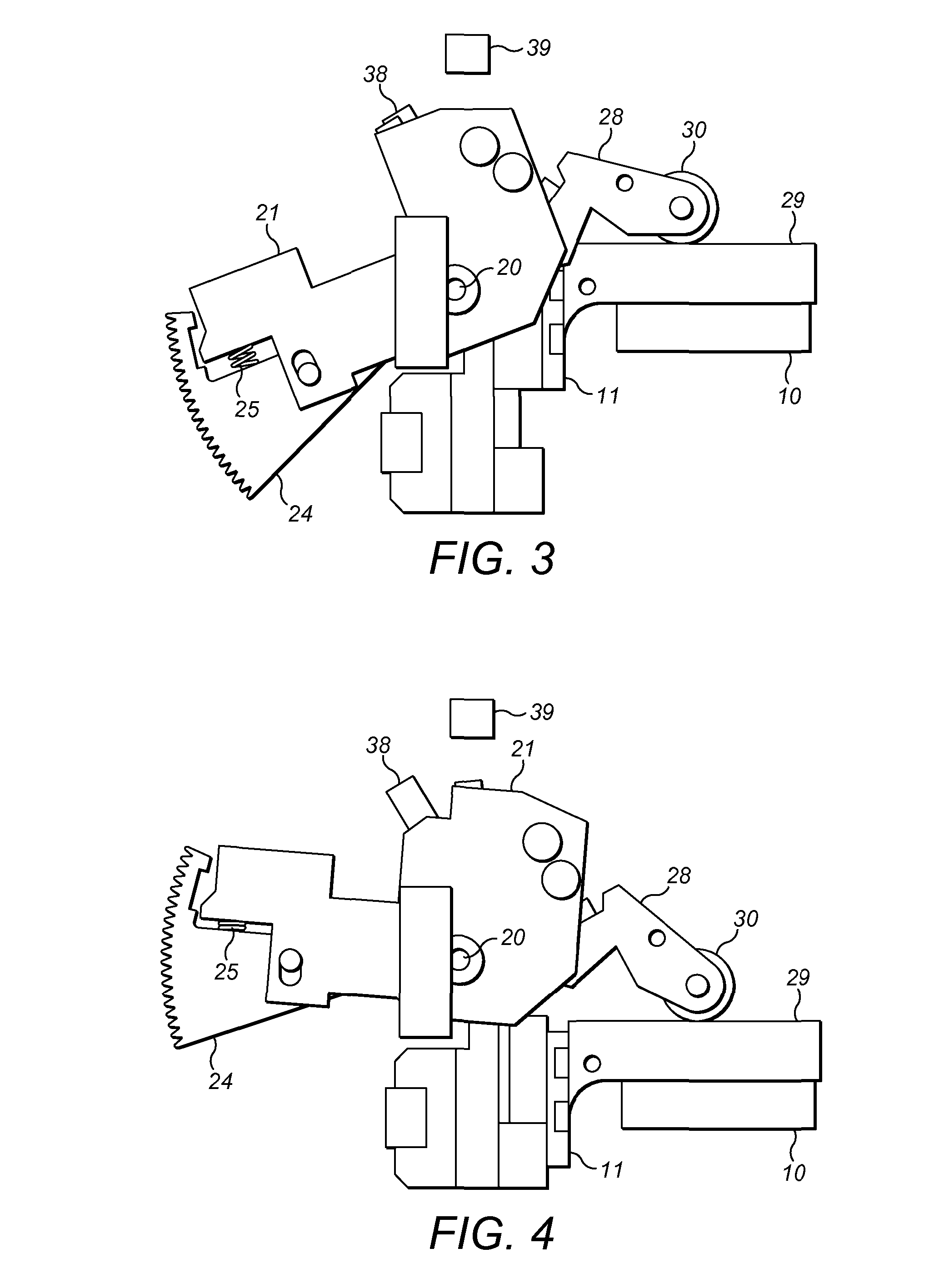
[0024]FIGS. 1 to 4 show a preferred form of a thermal transfer printing apparatus which embodies the various aspects of the invention. In the form shown a thermal print head 10 is attached to a carriage 11 that allows the print head to move in a vertical direction towards and away from a substrate support 12. The substrate support 12 may be part of the apparatus or may be provided as part of the environment in which, in use, the apparatus is mounted.

[0025]The carriage 11, in turn, is attached to a drive belt 13 that allows the print head to be moved in both directions along a horizontal axis. To this end the belt is mounted on a pair of spaced rollers 14 and it will be appreciated that the direction of rotation of the rollers 14 determines the direction of movement of the carriage 11 in a horizontal direction.

[0026]In the conventional manner, lowering the print head 10 toward the substrate support 12, displaces an ink-impregnated ribbon or tape 15 into contact with a substrate 16 su...


PUM


Abstract

The invention provides a method of controlling the pressure applied to a substrate being printed by a thermal transfer printing head. The head displacement facility includes a resilient member such as a spring which undergoes deflection as the print head engages the substrate. The method comprises monitoring both print head position and spring deflection to control the pressure applied by the print head.

Description

FIELD OF THE INVENTION[0001]This invention relates to printing apparatus and, in particular, to thermal transfer printing apparatus.BACKGROUND TO THE INVENTION[0002]Thermal transfer overprinting apparatus normally includes a thermal printing head having a linear or 2-dimensional array of thermal elements. In use the thermal printing elements are selectively energised in accordance with data representative of an image to be printed, e.g. the output data from a computer, or a scanning device. The thermal head is brought into contact with a ribbon or tape bearing a hot melt ink or wax, sandwiching the ribbon or tape between the thermal head and a substrate. The selective energising of the elements in the thermal head then initiates transfer of the hot melt ink from the ribbon to the substrate.[0003]It is recognised by those versed in the art that the print quality provided by a thermal printing head is highly dependent on the pressure applied by the thermal head to the substrate being ...

Claims


Application Information

Patent Timeline
Patent Type & Authority Patents(United States)
IPC IPC(8): B41J29/393B41J25/312B41J2/335
CPCB41J25/312B41J29/393
Inventor MORGAN, JONATHANKIILERICH, EBBEJORGENSEN, KRISTIAN VAN
Owner DOMINO PRINTING SCIENCES
Why Eureka
Try Eureka