Heat exchanger

a technology of heat exchanger and cassette, which is applied in the direction of manufacturing tools, soldering devices, light and heating equipment, etc., can solve the problems of reducing the maximum allowed pressure in the cassette, accumulating more material, etc., and achieves convenient cassette assembly, reliable joint, and convenient cassette assembly.

Active Publication Date: 2015-01-27
ALFA LAVAL CORP AB
View PDF23 Cites 3 Cited by
  • Summary
  • Abstract
  • Description
  • Claims
  • Application Information

AI Technical Summary

Benefits of technology

[0011]By this first embodiment of the plate for a heat exchanger, a gasket groove of the plate used for the permanent joining of two plates into a cassette is adapted such that the joint of the cassette is improved. In this way, an airtight joint is possible to obtain in a reliable and cost-effective way. The problems caused by the tolerances in the joining process are, depending on type of problem, lowered or eliminated.
[0023]In an inventive method for assembling heat exchanger cassettes, using heat exchanger plates according to the invention, the steps of applying brazing solder solely on at least one of the second, bent sections of the heat exchanger plates, assembling the two plates to each other, and brazing the cassette in a brazing process are comprised. The advantage of the method is that the brazing solder is not applied on the surfaces that will bear on each other. By this, the positioning of one plate to the other is improved, since there is no brazing solder on the bearing surfaces that will interfere with the positioning of the plates.

Problems solved by technology

One problem in using plate heat exchangers for e.g. the food industry is that some products contain fibres and other solid materials mixed in the fluid.
Such an arrangement is cost-effective and works for many applications, but shows some drawbacks when it comes to beverages and other products that comprises fibres and other solid materials, since the plates will bear on each other at some contact points.
A drawback of the plates bearing on each other is that each bearing point will constitute a flow restriction where material contained in the liquid may be trapped and can accumulate.
The accumulated material will restrict the flow further, causing more material to accumulate.
Especially if the heating / cooling fluid will have a relatively high pressure, even a small leakage will cause problems.
Tolerances in the plates and / or the joining technique may give an imperfect result or may reduce the maximal allowed pressure in the cassette.

Method used


Image

  • Heat exchanger
  • Heat exchanger
  • Heat exchanger

Examples


Embodiment Construction

[0029]The embodiments of the invention with further developments described in the following are to be regarded only as examples and are in no way to limit the scope of the protection provided by the patent claims.

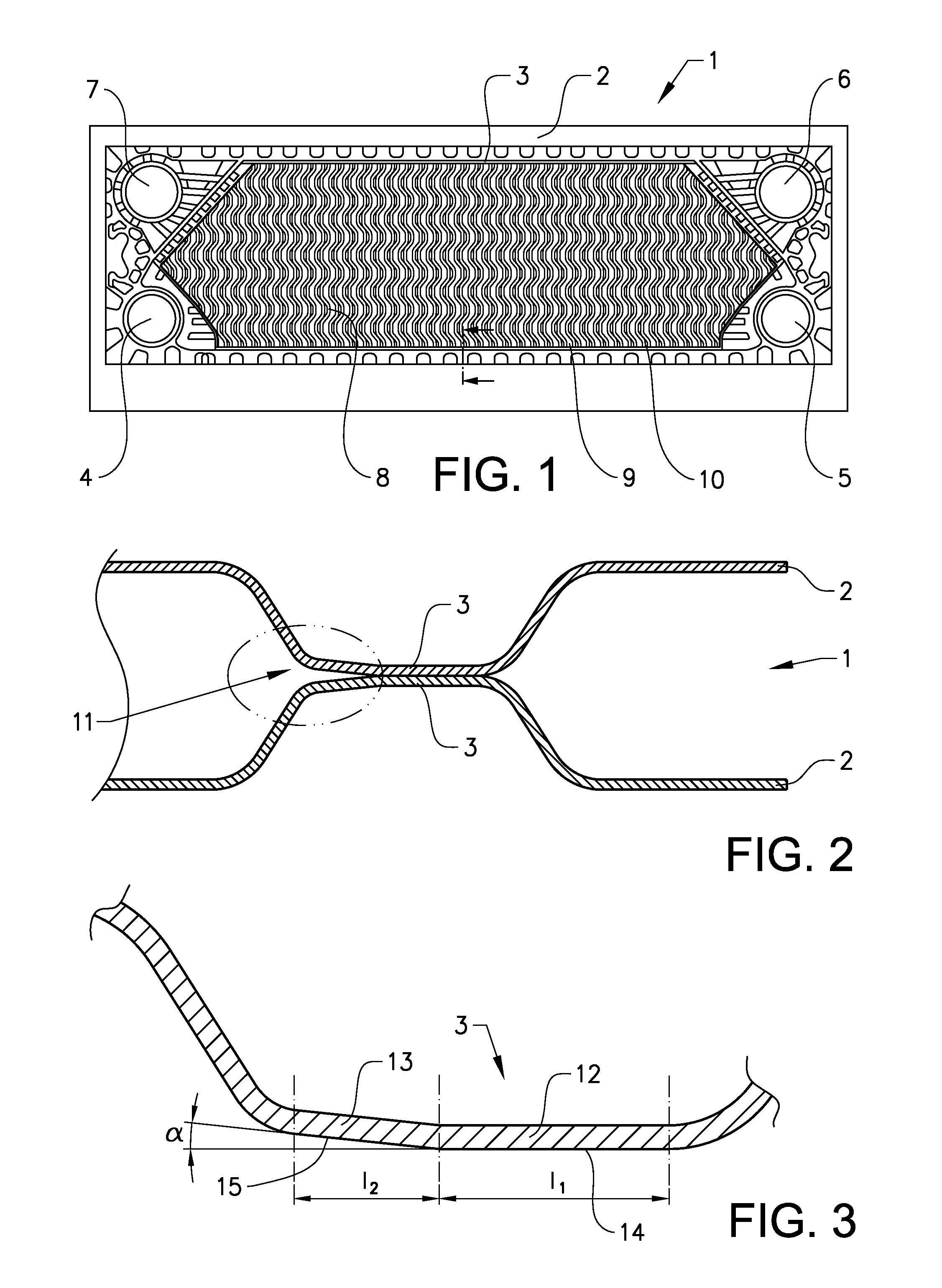
[0030]FIG. 1 shows a front view of a cassette 1 for the use in a heat exchanger according to the invention. The cassette 1 comprises two heat exchanger plates 2 permanently joined together. The plates have at least four portholes constituting inlet and outlet ports 4, 5, 6, 7 and a heat transfer surface 8 with ridges 9 and valleys 10. The cassette 1 is produced by brazing the plates together, whereby the two plates 2 are joined together permanently along their periphery, at the diagonal gasket groove and around at least two of ports 4, 5, 6, 7. Preferably, the plates are joined also in the heat transfer surface, where the pattern of one plate will bear on the pattern of the other plate. The plates may e.g. be joined along a few longitudinal lines reaching from one inlet / out...


PUM

PropertyMeasurementUnit
angleaaaaaaaaaa
angleaaaaaaaaaa
angleaaaaaaaaaa

Abstract

A plate for the use in a heat exchanger cassette, where the plate comprises a corrugated pattern having a plurality of ridges (9) and valleys (10), and where the plate comprises a sealing gasket groove (3) encircling a heat transfer surface (8) that will be part of a contact-free fluid channel when two cassettes comprising at least one plate each are positioned adjacent each other, wherein the sealing gasket groove (3) comprises a base surface with a first, flat section (12) and a second, bent section (13), and where the bent section is angled with the angle α. The advantage of the inventive plate is that an airtight heat exchanger cassette can be obtained in an easy and cost-effective way.

Description

TECHNICAL FIELD[0001]The present invention relates to a heat exchanger plate for a plate heat exchanger having a contact-free distribution passage. The invention also relates to a cassette comprising two heat exchanger plates for a plate heat exchanger having a contact-free distribution passage. The invention further relates to a heat exchanger comprising a plurality of heat exchanger cassettes. The invention further relates to a method for assembling a cassette comprising two heat exchanger plates.BACKGROUND ART[0002]Food manufacture is typically characterised by the need to process and treat highly viscous products, e.g. concentrates for carbonated beverages, juices, soups, dairy products and other products of fluid consistency. For natural reasons, the hygiene aspirations and expectations in this context are extremely high to enable the requirements of various authorities to be met.[0003]Plate heat exchangers are used in the industry for a number of different purposes. One proble...

Claims


Application Information

Patent Timeline
Patent Type & Authority Patents(United States)
IPC IPC(8): F28F3/08B21D53/04B23P15/26B23K1/00F28D9/00F28F3/10
CPCF28D9/005B23K1/0012F28F3/083F28F3/10B23K2201/14F28F2275/04Y10T29/49393Y10T29/49366B23K2101/14F28D9/00F28F3/00
Inventor KRANTZ, JOAKIMWALTER, KRISTIAN
Owner ALFA LAVAL CORP AB
Why Eureka
Try Eureka