Eureka AIR delivers breakthrough ideas for toughest innovation challenges, trusted by R&D personnel around the world.

Wood screw

a technology of wood screws and retainers, applied in the direction of screws, washing machines, ways, etc., can solve the problems of frictional heat, surface breakage of retainer elements, expansion, frictional heat, etc., to prevent the retainer element from rotating with certainty, facilitate handling, and facilitate the effect of bending

Active Publication Date: 2015-01-27
TANEICHI KAORU
View PDF14 Cites 2 Cited by
  • Summary
  • Abstract
  • Description
  • Claims
  • Application Information

AI Technical Summary

Benefits of technology

The present invention is aimed at providing a wood screw that can securely hold a retainer element to a wood material without causing frictional heat and prevent breakage of the retainer element. The invention achieves this by efficiently attaching the retainer element to the wood screw and preventing rotation of the wood screw that can lead to breakage of the retainer element. Additionally, the invention addresses the issue of horizontal misalignment between the wood material and the retainer element by changing the misalignment to that between the truncated cone-shaped washer and the head of the wood screw main body, thereby preventing breakage of the retainer element. The invention also ensures the washer does not detach from the wood screw main body, facilitating handling and use of the wood screw.

Problems solved by technology

Therefore, friction, expansion, and frictional heat occur.
The head of the wood screw becomes embedded further into the retainer element than expected, causing a drawback in that the surface of the retainer element breaks.

Method used


Image

  • Wood screw
  • Wood screw
  • Wood screw

Examples


first embodiment

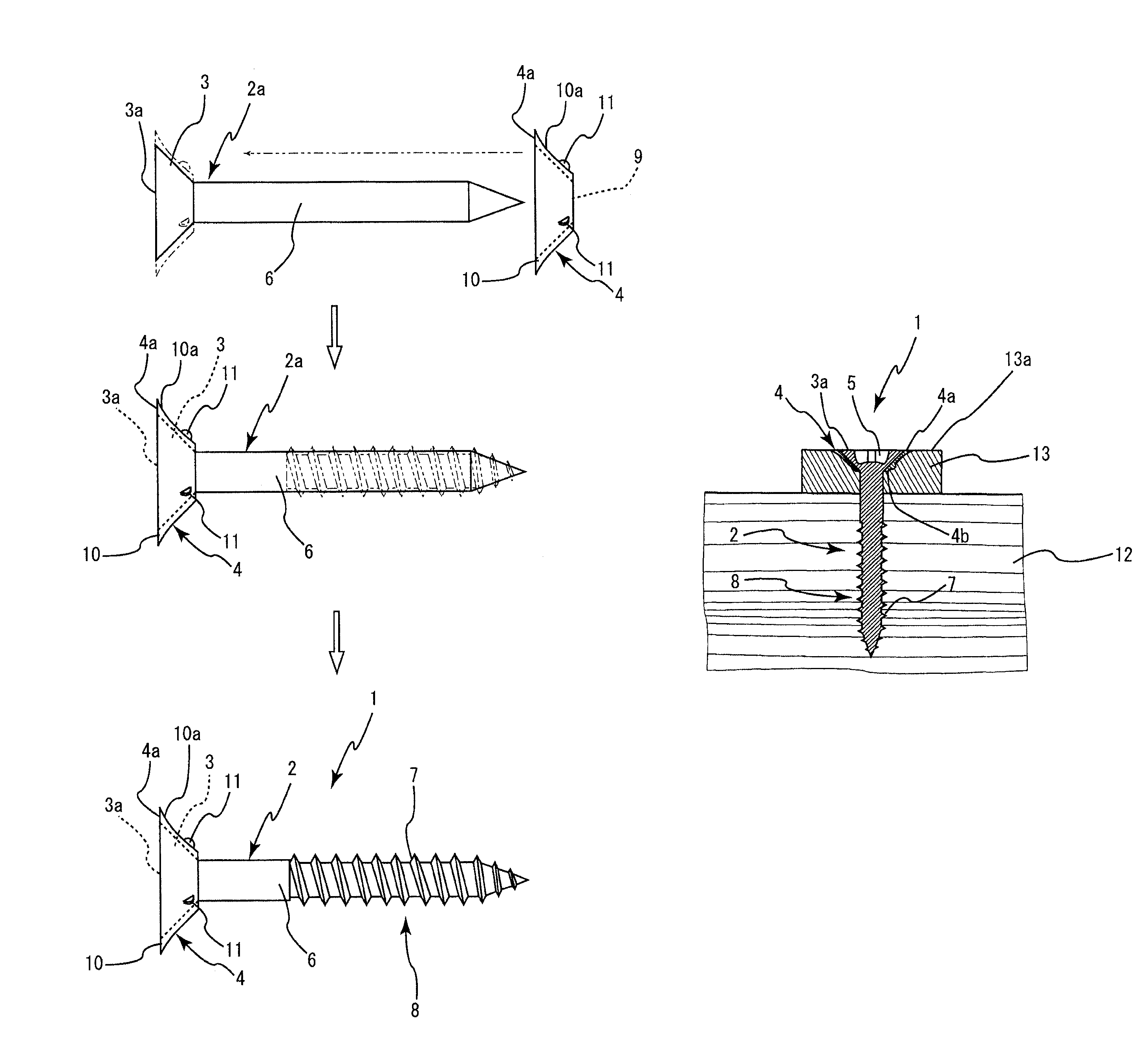
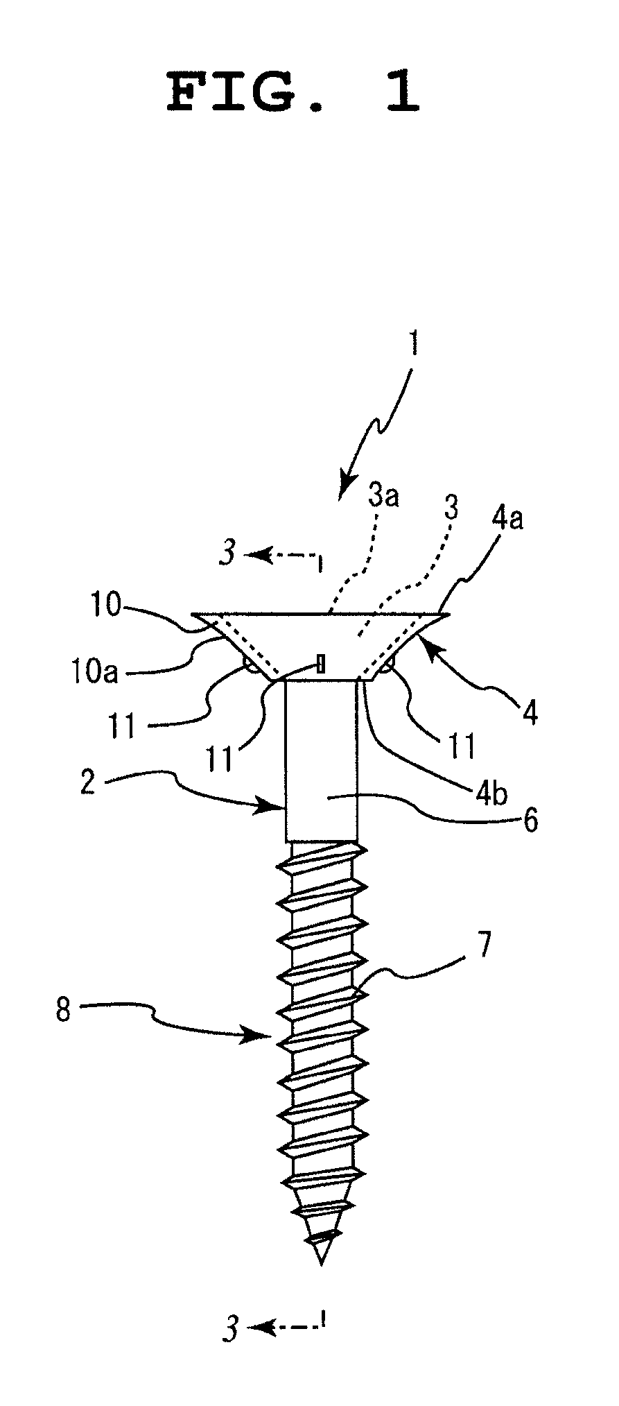
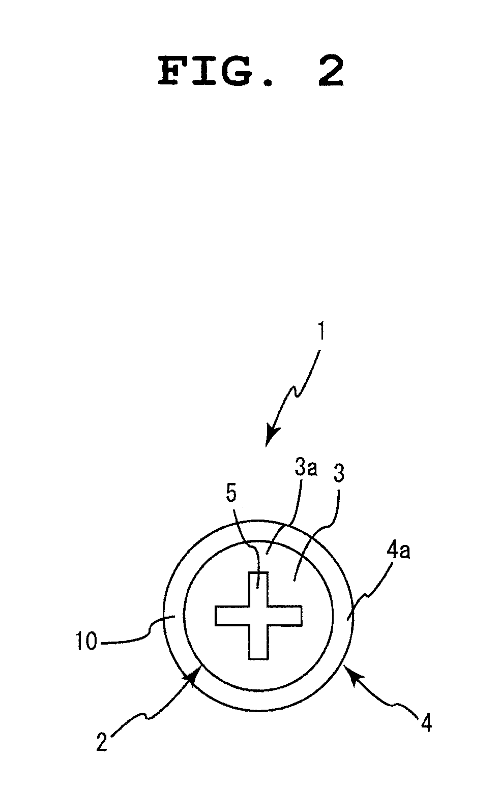
[0038]According to the present invention shown in FIG. 1 to FIG. 10, reference number 1 represents a wood screw of the present invention. The wood screw 1 is configured by a wood screw main body 2 and a truncated cone-shaped washer 4. The truncated cone-shaped washer 4 is rotatable in relation to a head 3 of the wood screw main body 2 such that a top surface 3a of the head and a top surface 4a of the washer 4 are substantially on the same plane, and is attached so as not to detach from the head 3.

[0039]An engaging groove 5 that engages with a Phillips screwdriver is formed in a truncated conical-shape in the head 3 of the wood screw main body 2. The wood screw 1 is also configured by a screw section p with a shaft section 6, integrally formed with the head section 3, provided between the screw section 8 and the head section 3. A tapping screw 7 is formed on the outer peripheral portion of the screw section 8, in which the diameter on the shaft section 6 side is larger than the outer...

second embodiment

[0047]the present invention shown in FIG. 11 to FIG. 13 differs from the first embodiment of the present invention in that a truncated cone-shaped washer 4A in which rotation-preventing projections are not formed is used. Even in a wood screw 1A configured using a truncated cone-shaped washer 4A such as this, similar operational effects as those according to the first embodiment of the present invention can be achieved.

third embodiment

[0048]the present invention shown in FIG. 14 to FIG. 16 differs from the first embodiment of the present invention in that a truncated cone-shaped washer 4B that can be removably attached to the wood screw main body 2 is used. Even in a wood screw 1B configured using a truncated cone-shaped washer 4B such as this, similar operational effects as those according to the first embodiment of the present invention can be achieved.


PUM

PropertyMeasurementUnit
lengthaaaaaaaaaa
axial heightaaaaaaaaaa
diameteraaaaaaaaaa

Abstract

The present invention is configured by a wood screw main body, and a truncated cone-shaped washer that is rotatable in relation to a head of the wood screw main body such that a top surface of the head and a top surface of the truncated cone-shaped washer are substantially on the same plane, and attached so as not to detach from the head. When a retainer element is secured by the wood screw to a wood material to be supported, frictional heat can be prevented from occurring in the retainer element, and the retainer element can be secured by only the fastening force of the wood screw. The retainer element can be efficiently prevented from breaking, and attached such that the head of the wood screw and the surface of the retainer element are on the same plane.

Description

BACKGROUND OF THE INVENTION[0001]The present invention relates to a wood screw.[0002]A conventional wood screw has a head that is formed into a truncated conical shape. The wood screw is used by being attached to a retainer element, such as a wood material, a board, or a cloth-adhered board, that is to be attached to a wood material to be supported, such that the head of the wood screw is on the same plane as the surface of the retainer element.[0003]However, when the wood screw is embedded into the retainer element, the head rotates while pressing against the retainer element by the rotation of the wood screw. Therefore, friction, expansion, and frictional heat occur. The head of the wood screw becomes embedded further into the retainer element than expected, causing a drawback in that the surface of the retainer element breaks.[0004]Japanese Patent Laid-open Publication No. 2001-289223 is related prior art.SUMMARY OF THE INVENTION[0005]In light of conventional drawbacks such as th...

Claims


Application Information

Patent Timeline
Patent Type & Authority Patents(United States)
IPC IPC(8): F16B43/00
CPCF16B25/0015F16B43/00
Inventor TANEICHI, KAORU
Owner TANEICHI KAORU
Why Eureka
Eureka Blog
Learn More