Converter control device and air conditioner including converter control device

a converter control and control device technology, applied in the direction of dynamo-electric converter control, motor/generator/converter stopper, heating type, etc., can solve the problems of increasing the size of the anti-noise measure part, increasing the manufacturing cost, and complicated anti-noise measure parts

Inactive Publication Date: 2015-01-27
MITSUBISHI ELECTRIC CORP
View PDF28 Cites 22 Cited by
  • Summary
  • Abstract
  • Description
  • Claims
  • Application Information

AI Technical Summary

Benefits of technology

[0053]The converter control device according to the present invention can achieve distribution of frequency components of noise generated from a converter main circuit and reduction of peak noise while maintaining the efficiency and generated loss of the converter main circuit in the same levels as the efficiency and generated loss of a conventional converter main circuit.

Problems solved by technology

In addition, because a conducting path of the conduction noise is complicated, an anti-noise measure to prevent noise propagation and leakage to other parts is also complicated.
This design style causes increase of a manufacturing cost, such as increase in size of an anti-noise measure part and increase of the number of parts.
Therefore, when designing electric appliances, noise filters for limiting conduction noise need to be connected in a multi-stage configuration using a large number of noise filter parts, and this causes a problem of increasing a those parts' occupying area in a board and also increasing the manufacturing cost.
Generally, switching noise of a semiconductor element tends to increase as an alternate-current power source voltage becomes higher.
Therefore, in the control described in Patent Literature 1, the caused noise is increased although the power conversion efficiency is enhanced, and there has been a problem in that it is not possible to execute the control while considering both of the amount of caused noise and loss generation that are in a tradeoff relationship with each other.

Method used


Image

  • Converter control device and air conditioner including converter control device
  • Converter control device and air conditioner including converter control device
  • Converter control device and air conditioner including converter control device

Examples


first embodiment

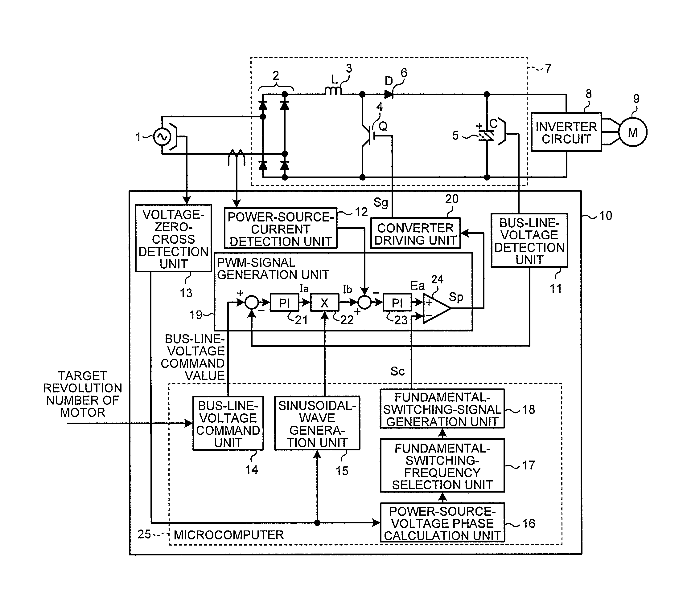
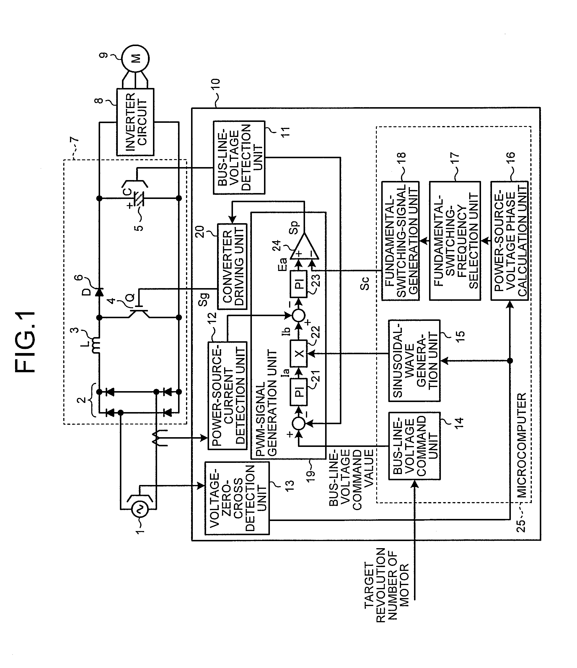
[0020]FIG. 1 is a diagram showing a system configuration of an air conditioner including a converter control device 10 according to a first embodiment of the present invention. As shown in FIG. 1, a converter main circuit 7 is constructed of a rectifying circuit 2, a reactor 3, a switching unit 4, a smoothing capacitor 5, and a back-flow preventing diode 6. The rectifying circuit 2 has four diodes connected in a bridge configuration for full-wave-rectifying an alternate-current voltage supplied from an alternate-current power source 1. The reactor 3 has a first end and a second end, of which the first end is connected to a positive output side of the rectifying circuit 2, and smoothes a current. The switching unit 4 is connected between the second end of the reactor 3 and a negative output side of the rectifying circuit 2, and performs switching between direct-current bus lines. The smoothing capacitor 5 is connected between the second end of the reactor 3 and the negative output si...

second embodiment

[0043]The converter control device according to the first embodiment changes the frequency of the converter driving signal Sg based on the phase of the alternate-current power source voltage. Meanwhile, in a second embodiment of the present invention, a converter control device that changes the frequency of the converter driving signal Sg based on the number of cycles of the alternate-current power source voltage. In the following explanations, the number of cycles is a time obtained by counting cycles in units of one cycle of an alternate-current power source voltage.

[0044]A configuration of the converter control device according to the second embodiment is shown in FIG. 5. A difference from the configuration of the first embodiment (FIG. 1) is that a power-source-voltage cycle-number computation unit 26 and a fundamental-switching-frequency selection unit 27 are provided instead of the power-source-voltage phase calculation unit 16 and the fundamental-switching-frequency selection...


PUM


Abstract

A converter control device comprises: a voltage-zero-cross detection unit detecting zero cross of the alternate-current voltage and outputting a voltage zero-cross signal; a power-source-current detection unit detecting a power source current of the alternate-current power source; a bus-line-voltage detection unit detecting a bus-line voltage between terminals of the smoothing capacitor; a PWM-signal generation unit generating a PWM-signal for on / off-controlling the switching unit, based on the power-source current, the bus-line voltage and a bus-line-voltage command value as a target voltage of the bus-line voltage; a power-source voltage-state detection unit detecting a signal state of the alternate-current voltage based on the voltage zero-cross signal; and a fundamental-switching-frequency selection unit selecting a fundamental switching frequency of the PWM-signal based on the signal state of the alternate-current voltage. The PWM-signal generation unit generates the PWM-signal based on a fundamental switching signal having a fundamental switching frequency selected by the fundamental-switching-frequency selection unit.

Description

BACKGROUND OF THE INVENTION[0001]1. Field of the Invention[0002]The present invention relates to a converter control device that controls a highly-efficient converter installed in an air conditioner and an air conditioner including the converter control device.[0003]2. Description of the Related Art[0004]There is known a conventional converter control device that obtains a rectified voltage by rectifying an alternate-current power source voltage with a rectifying circuit such as a diode bridge, and improves the power factor using a voltage-boosting reactor and a semiconductor switching element such as a metal-oxide semiconductor field-effect transistor (MOSFET) that is on / off controlled by pulse width modulation (PWM) control. The PWM control of the semiconductor switching element is executed using a triangular wave signal having a constant fundamental switching frequency, and therefore a frequency component of conduction noise caused with the on / off operation of the semiconductor s...

Claims


Application Information

Patent Timeline
Patent Type & Authority Patents(United States)
IPC IPC(8): H02P27/08F24F5/00H02M7/06
CPCH02M1/4225Y02B70/10H02M7/06H02P27/08
Inventor OTORII, YUSAITO, KATSUHIKOFUKUDA, MASAHIRO
Owner MITSUBISHI ELECTRIC CORP
Why Eureka
Try Eureka