Image forming apparatus

a technology coupler, which is applied in the direction of electrographic process apparatus, instruments, optics, etc., can solve the problems of increasing manufacturing costs, increasing the number of parts, and difficulty in reducing the size and achieve the effect of image forming apparatus

Active Publication Date: 2015-01-27
HEWLETT PACKARD DEV CO LP
View PDF10 Cites 0 Cited by
  • Summary
  • Abstract
  • Description
  • Claims
  • Application Information

AI Technical Summary

Benefits of technology

[0010]The present inventive concept provides an image forming apparatus in which a driving structure to drive a developing cartridge mounted in a main body of the image forming apparatus is simplified.
[0011]The present inventive concept also provides an image forming apparatus with an improved driving structure in which the developing cartridge mounted in the main body of the image forming apparatus is stably mounted or separated.

Problems solved by technology

However, the number of stationary cams is increased in correspondence to that of the rotary cams, thereby increasing the number of parts and increasing manufacturing costs.
Also, a space in which the stationary cam is installed is increased, and therefore, it may be difficult to decrease the size of the image forming apparatus.
For the horizontal cam, on the other hand, the direction in which force is applied from the horizontal cam to the rotary cam is different from the direction in which the rotary cam is moved, and therefore, it may be difficult to stably move the coupler as compared with the stationary cam.

Method used


Image

  • Image forming apparatus
  • Image forming apparatus
  • Image forming apparatus

Examples


Embodiment Construction

[0062]Reference will now be made in detail to the embodiments of the present general inventive concept, examples of which are illustrated in the accompanying drawings, wherein like reference numerals refer to the like elements throughout. The embodiments are described below in order to explain the present general inventive concept while referring to the figures.

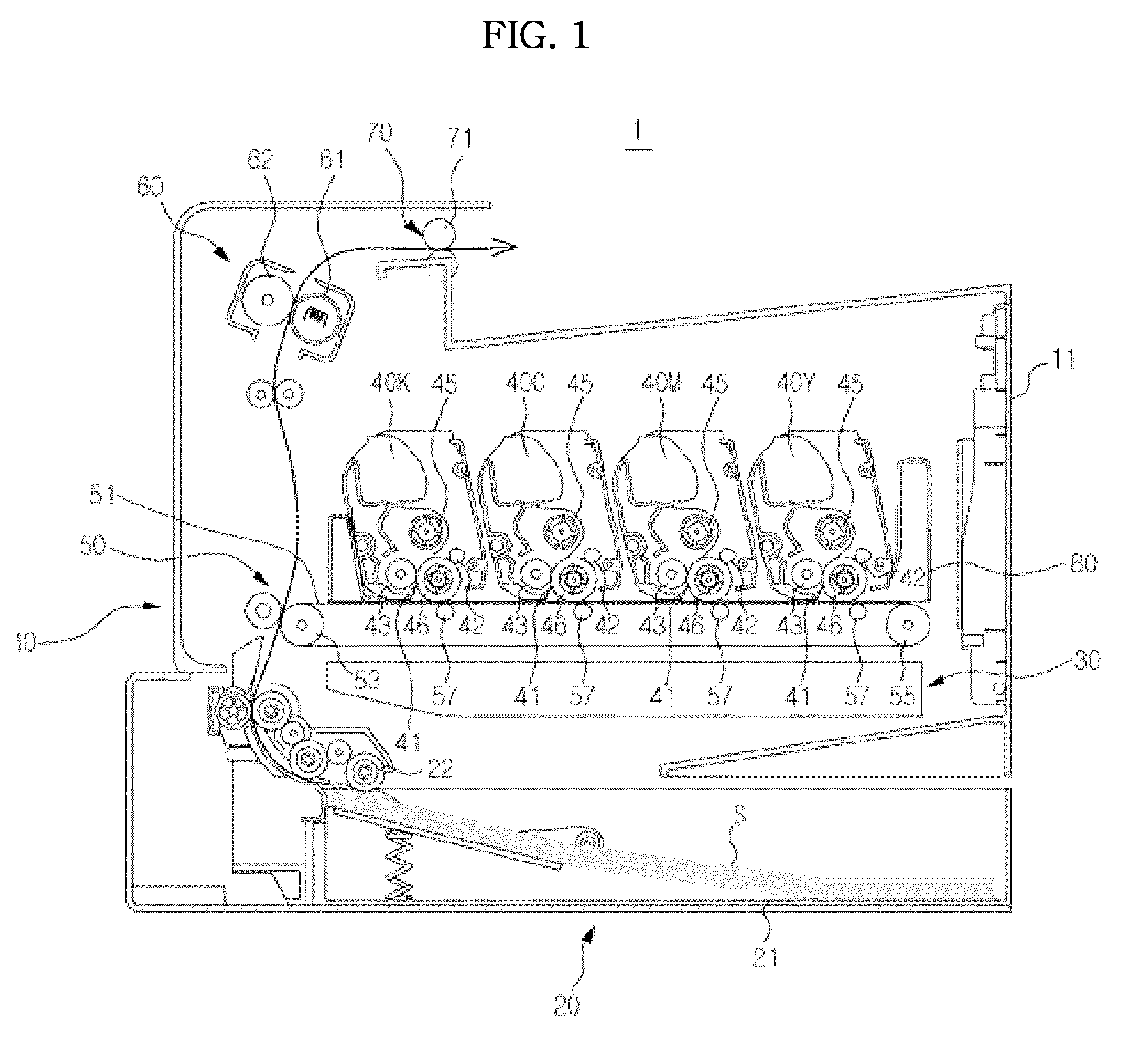
[0063]FIG. 1 is a view schematically showing the construction of an image forming apparatus according to an exemplary embodiment of the present inventive concept.

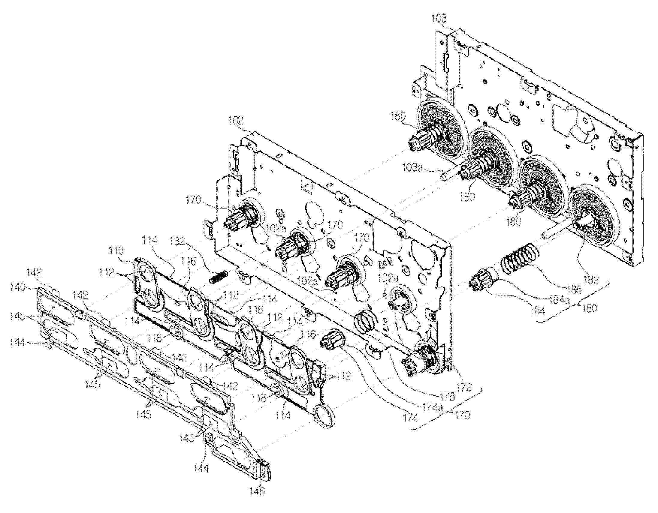
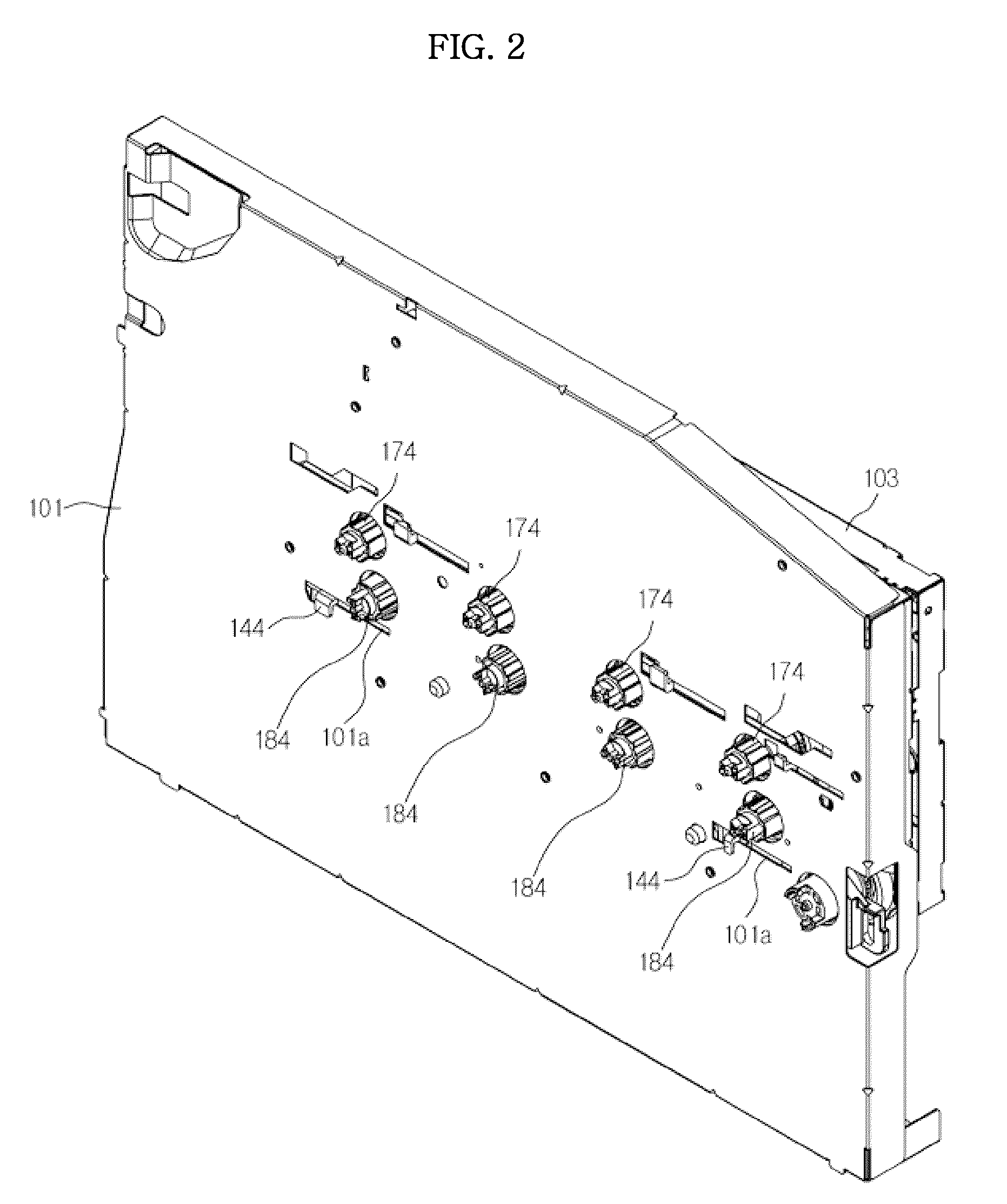
[0064]As shown in FIG. 1, an image forming apparatus 1 includes a main body 10, a print media supply unit 20, an optical scanning unit 30, a developing cartridge 40, a transfer unit 50, a fusing unit 60, and a print media discharge unit 70.

[0065]The main body 10 forms the external appearance of the image forming apparatus 1 and supports various components installed therein. A cover 11 is rotatably installed at one side of the main body 10. The cover 11 opens and clos...


PUM


Abstract

An image forming apparatus includes a main body, a cover to open and close a front of the main body, a tray slidably mounted in the main body through the front of the main body, at least one developing cartridge mounted in the main body in a state in which the developing cartridge is received in the tray, at least one driving coupler member provided at one side of the main body to drive the developing cartridge mounted in the main body, a link member operating simultaneously with opening and closing of the cover to move in a first direction, and a guide member to support the at least one driving coupler member, the guide member operating simultaneously with the link member to move in a second direction perpendicular to the first direction, wherein the guide member is pressed by the link member, when the cover opens the main body, to separate the driving coupler member from the developing cartridge.

Description

CROSS-REFERENCE TO RELATED APPLICATIONS[0001]This application claims the benefit of Korean Patent Application No. 2011-0104017, filed on Oct. 12, 2011 in the Korean Intellectual Property Office, the disclosure of which is incorporated herein by reference in its entirety.BACKGROUND OF THE INVENTION[0002]1. Field of the Invention[0003]Embodiments of the present inventive concept relate to an image forming apparatus with a driving structure to drive a developing cartridge.[0004]2. Description of the Related Art[0005]An image forming apparatus forms an image on printing media according to an input signal. The image forming apparatus includes a printer, copier, facsimile and a multifunction device having functions of the printer, copier, and facsimile.[0006]An electrophotographic image forming apparatus, which is a kind of image forming apparatus, includes a developing cartridge including an image carrier and a developing device and an optical scanning unit. The optical scanning unit sca...

Claims


Application Information

Patent Timeline
Patent Type & Authority Patents(United States)
IPC IPC(8): G03G21/16G03G15/00G03G15/08
CPCG03G15/0896G03G21/1623G03G21/1647
Inventor KIM, TAE HEEJEONG, GI CHEOL
Owner HEWLETT PACKARD DEV CO LP
Why Eureka
Try Eureka