Spring force adjustment structure in high-hat stand and high-hat stand including the spring force adjustment structure

a technology of spring force adjustment and high-hat stand, which is applied in the direction of spring/damper, instruments, musical instruments, etc., can solve the problems of limited foot space, deterioration of usability, and the operability problem of the foregoing structure, so as to prevent a reduction in floor space, easy for a user and easy to understand the amount of adjustment

Inactive Publication Date: 2015-02-03
SAKAE RHYTHM MUSICAL INSTR
View PDF18 Cites 8 Cited by
  • Summary
  • Abstract
  • Description
  • Claims
  • Application Information

AI Technical Summary

Benefits of technology

[0020]In the spring force adjustment structure and the high-hat stand including the spring force adjustment structure according to the present invention, the coil spring and the spring force adjustment structure are provided in the stand main body, which eliminates the need to arrange a tubular body in parallel via a connection metal fitting at the lower end part of the stand main body to prevent a reduction in the floor space. Since the plurality of engagement steps different in height is circumferentially formed in a stair-like pattern in order of height at the supporting part of the adjustment member and / or the supported part of the extension part and the return spring rotating and biasing the adjustment member is provided in the direction in which the engagement steps supporting the extension part and / or the engagement steps supported by the adjustment member become gradually higher with respect to the stand main body, when the adjustment member is rotated in the direction in which the engagement steps supporting the extension part and / or the engagement steps supported by the adjustment member gradually become lower, the lock member descends along the elongated groove to adjust the spring force of the coil spring so as to be lower, and at that time, the adjustment member can be easily rotated with one hand. In addition, since the engagement steps are moved one by one in association with the rotation, it is easy for a user to understand the amount of adjustment made. When the lock member is moved upward, the spring force of the coil spring becomes higher and the adjustment member is biased and rotated by the return spring, and thus the engagement steps supporting the extension part and / or the engagement steps supported by the adjustment member support the extension part and / or are supported by the adjustment member at higher engagement steps, which makes it possible to adjust the spring force so as to be higher. At that time, the adjustment member can also be automatically turned through the return spring to the engagement position only by moving the lock member upward with one hand, which allows the adjustment operation to be performed without having to use both hands. In addition, since the engagement steps move one by one together with the upward movement operation, it is easy for a user to understand the amount of the adjustment made. That is, according to the present invention, it is easy to adjust the spring force with one hand in the both directions in which the spring force becomes weaker and stronger and understand the amount of the adjustment made. Therefore, it is also easy to estimate the amount of adjustment to be made when making a fine-tuning afterward and return the spring force to the state before the adjustment.
[0021]Since the present invention is structured in such a manner that the plurality of supporting parts and / or supported parts of the same stair-like structure is arranged in the circumferential direction, it is possible to support the lock member in a stable posture by the adjustment member at a plurality of positions, and it is possible to prevent that the lock member enters into an unstable posture and exerts adverse effect on the operation of the up / down rod.
[0022]In particular, since the present invention is structured in such a manner that the plurality of supporting parts and / or supported parts of the stair-like structure is positioned symmetric with respect to the axial center of the stand main body, it is possible to support the lock member in a more stable posture.
[0023]In addition, since the present invention is structured in such a manner that the adjustment member includes the annular base part that locks the other end side of the return spring locked at the one end side onto the outer peripheral part of the stand main body and arranged in the circumferential direction, onto the inner peripheral surface side of the stand main body, and is rotated with an outer peripheral surface thereof as a grip part, and the supporting part provided on an upper surface side of the annular base part, it is possible to arrange efficiently the return spring on the inside of the annular base part with an increased outer peripheral diameter for enhancement of operability, thereby allowing the adjustment member to be made compact at lower costs.
[0024]Further, since the present invention is structured in such a manner that the adjustment member has the tubular part covering the supporting part on the outer peripheral surface side of the supporting part and the lock member has the tubular operation cover extended downward along the outer peripheral surface of the tubular part of the adjustment member on the outer side of the portion of the extension part opposed to the supporting part, the supporting part and the supported part are shielded from the outside by the outer tubular part and the operation cover, respectively. Accordingly, the engagement cannot be seen from the outside, which achieves a preferably simple design of the stand. In addition, it is possible to achieve tight engagement without entry of any foreign object such as dust into the engagement part, assure smooth adjustment operations, and prevent the user from getting his / her fingers pinched at the engagement during execution of the adjustment operations.

Problems solved by technology

This causes a problem of a further reduction in a limited foot space in the presence of the stand leg and the pedal, thereby leading to deterioration of usability.
Such an adjustment operation using both hands is troublesome and thus the foregoing structure has a problem of operability.
In addition, it is hard for a user to decide the amount of raising the lock member if he or she is not careful.
In the case where the user temporarily raises the lock member and then wishes to fine-tune the height of the lock member afterward, he or she cannot understand to what degree to turn the adjustment member to lower the lock member, and as a result, he or she cannot return the lock member even to the state before the adjustment.
In this structure, however, to adjust the spring force, it is necessary to perform a complicated operation of rotating temporarily the rotary knob to release the positioning projection from the engagement groove in the sleeve and then moving the positioning projection again in the axial direction to fit the positioning projection into another engagement groove.
In addition, in the foregoing structure, the positioning projection is not to be moved one by one between the engagement grooves, and thus if the user is not careful, it is hard for him or her to understand how many engagement grooves are passed between before and after movement of the positioning projection in the axial direction.
Therefore, in the case where the user adjusts temporarily the spring force and then wishes to fine-tune the spring force again afterward, he or she cannot understand with what engagement groove to engage the positioning projection unless he or she memorize the position of the positioning projection before the adjustment, and thus cannot return the positioning projection even to the state before the adjustment.

Method used


Image

  • Spring force adjustment structure in high-hat stand and high-hat stand including the spring force adjustment structure
  • Spring force adjustment structure in high-hat stand and high-hat stand including the spring force adjustment structure
  • Spring force adjustment structure in high-hat stand and high-hat stand including the spring force adjustment structure

Examples


Embodiment Construction

[0036]Next, embodiments of the present invention will be described in detail with reference to the attached drawings.

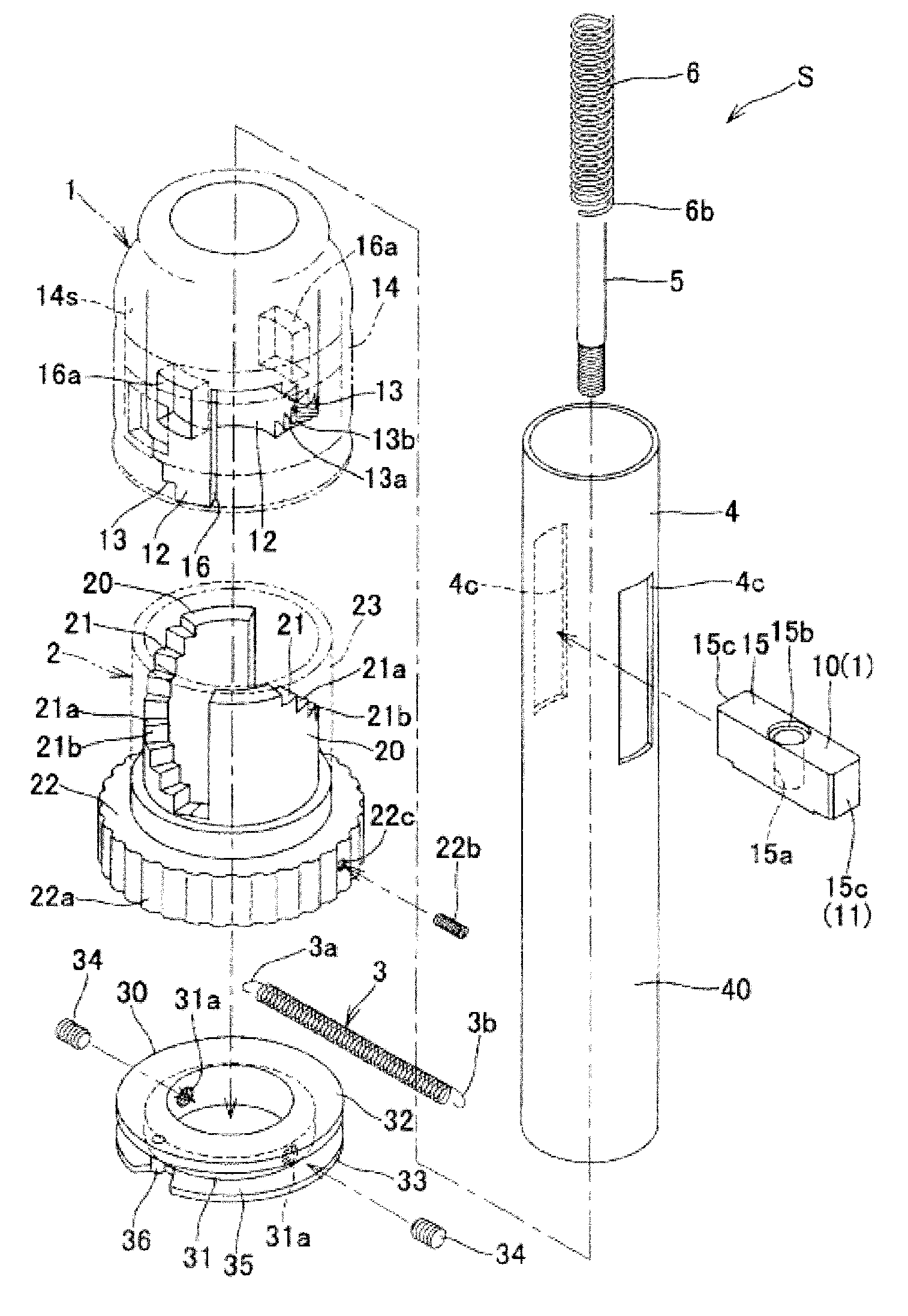
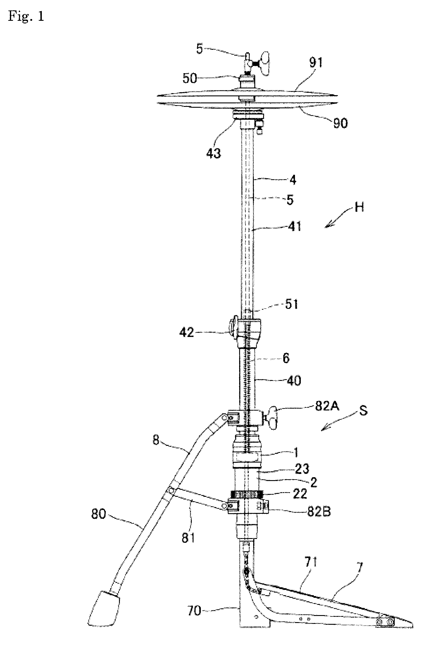
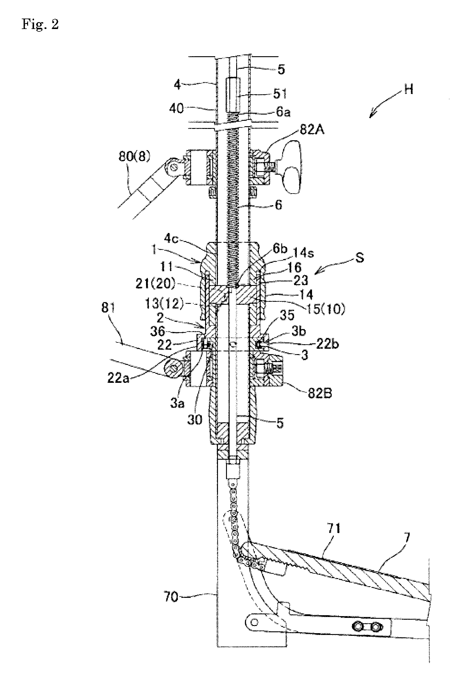
[0037]As shown in FIG. 1, a high-hat stand H including a spring force adjustment structure S as a typical example of the present invention includes: a tubular stand main body 4 that is supported by a stand leg 8 and a pedal device 7, and has an upper end part thereof to which a lower cymbal 90 is attached; an up / down rod 5 that is inserted into the stand main body 4, has a protruding upper end part at which an upper cymbal 91 is held, and has a lower end part to which a pedal 71 is connected; a coil spring 6 that is attached to the inside of the stand main body 4 and biases upward the up / down rod 5 locked onto an one end side 6a thereof to separate the upper cymbal 91 from the lower cymbal 90; and the spring force adjustment structure S adjusting a spring force (elastic restoring force / biasing force) of the coil spring 6.

[0038]The stand main body 4 is formed by a lowe...


PUM


Abstract

To provide a spring force adjustment structure in a high-hat stand that allows a user to easily adjust a spring force with one hand without reducing a floor space, easily understand the amounts of adjustments made, easily estimate the amount of adjustment to be made when making a fine-tuning afterward, and easily return the spring force to the state before the adjustment.

Description

TECHNICAL FIELD[0001]The present invention relates to a spring force adjustment structure in a high-hat stand.BACKGROUND ART[0002]High-hat stand includes a tubular stand main body in which a lower cymbal is attached to an upper end part thereof, an up / down rod that is inserted into the stand main body and has a protruding upper end part at which an upper cymbal is held, a pedal connected to the lower end of the up / down rod, a coil spring that biases the up / down rod in an upward direction, and a spring force adjustment device that adjusts a spring force of the coil spring, wherein the pedal is stepped on to lower the up / down rod together with the upper cymbal and strike the lower cymbal (for example, refer to Patent Document 1).[0003]The coil spring and the spring force adjustment device are configured such that a bar-like spring receiver is provided inside a tubular body provided in parallel with the lower end part of the stand main body and is connected to the lower end of the up / d...

Claims


Application Information

Patent Timeline
Patent Type & Authority Patents(United States)
IPC IPC(8): G10D13/02F16F1/12G10D13/06
CPCG10D13/065F16F1/121
Inventor NAKATA, EIZOTSUJI, SHUNSAKUMORIOKA, MANABU
Owner SAKAE RHYTHM MUSICAL INSTR
Why Eureka
Try Eureka