Non-pneumatic tire

a non-pneumatic tire and tire body technology, applied in the field of non-pneumatic tires, can solve the problems of limiting the application range, heavy weight of conventional non-pneumatic tires, and high hardness and high rolling resistance, and achieves uniform contact pressure distribution, convenient use, and convenient use.

Inactive Publication Date: 2015-02-10
BRIDGESTONE CORP
View PDF22 Cites 19 Cited by
  • Summary
  • Abstract
  • Description
  • Claims
  • Application Information

AI Technical Summary

Problems solved by technology

However, the conventional non-pneumatic tire has heavy weight, high hardness and high rolling resistance as compared with a pneumatic tire.
Accordingly, ride quality and maneuverability drastically deteriorate.
Therefore there is a limit to the application range thereof due to difficulties about the application to general vehicles.

Method used


Image

  • Non-pneumatic tire
  • Non-pneumatic tire
  • Non-pneumatic tire

Examples


first embodiment

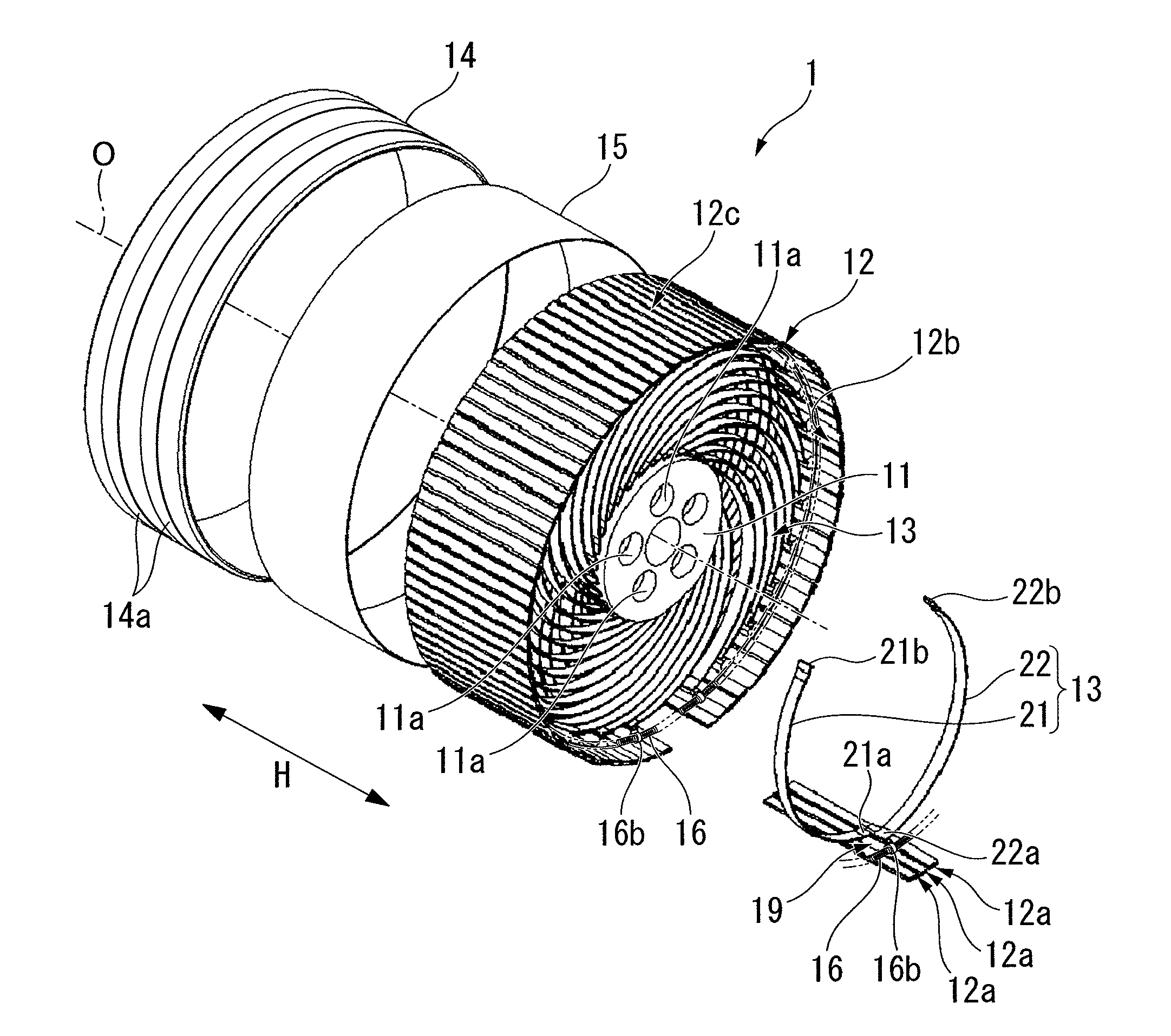
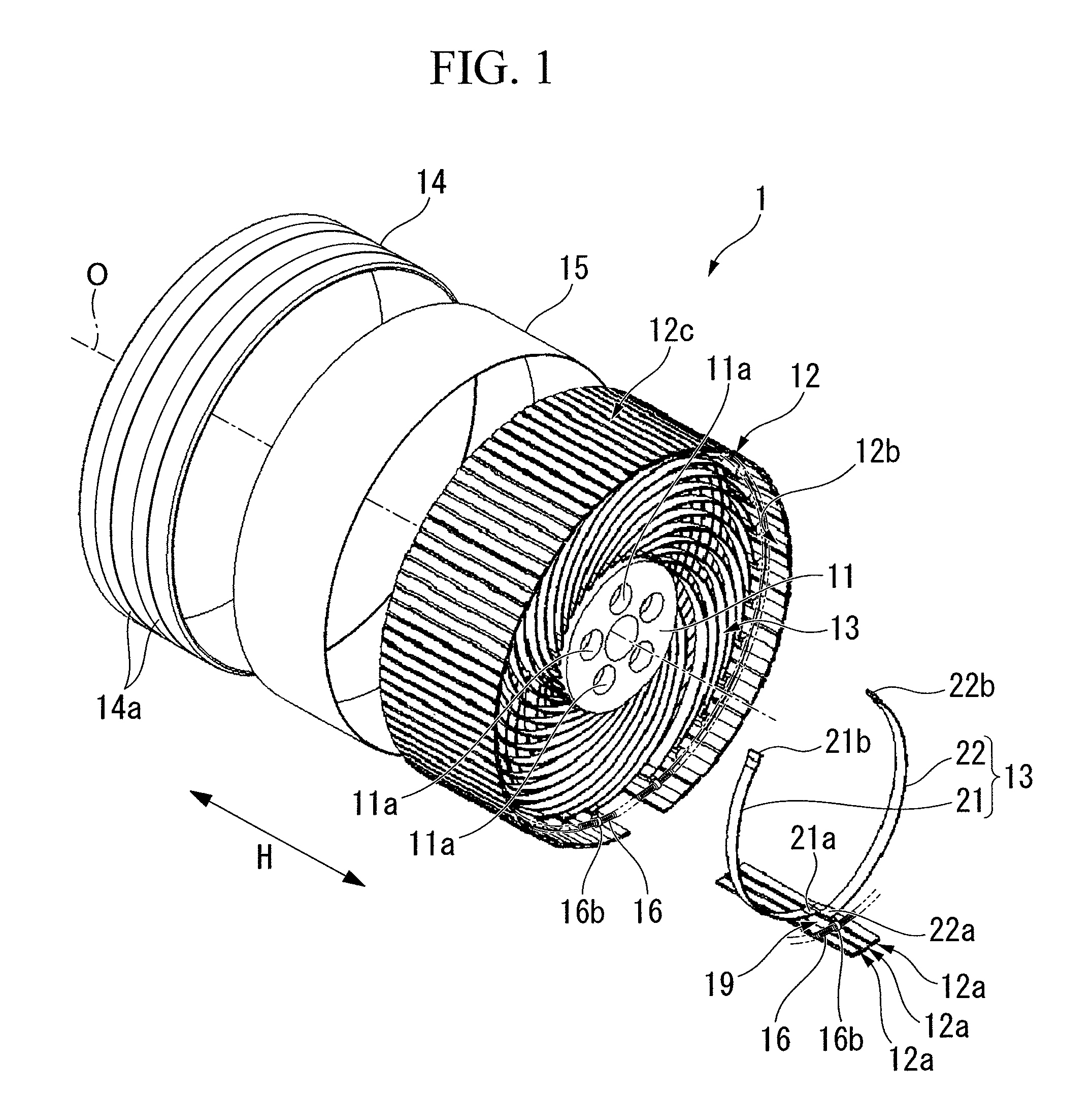
[0043]a non-pneumatic tire according to the present invention will be described hereafter making reference from FIG. 1 to FIG. 3B.

[0044]The non-pneumatic tire 1 is provided with an mounting body 11 mounted on an axle (not shown), an annular body 12 encircling the mounting body 11 from the outside in the tire-radial direction, a plurality of connecting members 13 that is disposed along the tire-circumferential direction and connects the outer circumferential face of the mounting body 11 and the inner circumferential face 12b of the annular body 12, a tread member 14 disposed over the entire outer circumferential face 12c of the annular body 12, and a reinforcing layer 15 disposed between the annular body 12 and the tread member 14.

[0045]The mounting body 11 has a circular shape in a side view of the non-pneumatic tire 1 from a direction of an axial line O, and a plurality of mounting holes 11a is formed at the radial center in the mounting body 11. For example, bolts are inserted int...

second embodiment

[0109]Furthermore in the second embodiment, although a configuration is described in which both first ends 21a, 22a and second ends 22b, 22b of both connecting plates 21, 22 are supported to rotate freely about the rotation axial line R, at least one of the first ends 21a, 22a and second ends 22b, 22b may be supported to rotate freely about the rotation axial line R.

[0110]In each of the above embodiments, the second ends 21b, 22b of both connecting plates 21, 22 are respectively connected to positions separated by the same angle within a range of for example, at least 45° to 135° or less, and preferably, as shown in FIG. 3 and FIG. 6, at least 90° to 120° or less, to the first side and the second side in the tire-circumferential direction about the axial line O from a position in the tire-radial direction facing each first end 21a, 22a on the outer circumferential surface of the mounting body 11. In this manner, both connecting plates 21, 22 can easily deform in response to an input...


PUM


Abstract

In a non-pneumatic tire (1), a plurality of connecting members (13) that connects a mounting body (11) and an annular body (12) are provided along a tire-circumferential direction. The annular body is split into a plurality of split bodies (12a) along the tire-circumferential direction. A resilient member (16) that is extended along the tire-circumferential direction and connects the plurality of split bodies in the tire-circumferential direction is provided in the annular body. This non-pneumatic tire (1) secures satisfactory ride quality, maneuverability and durability by suppressing increase in weight, hardness and rolling resistance, ensures uniform contact-pressure distribution, and prevents the occurrence of a puncture.

Description

TECHNICAL FIELD[0001]The present invention relates to a non-pneumatic tire which does not require filling its inside with pressurized air when used.[0002]This application claims the benefit of Japanese Patent Application 2008-178656 filed in Japan on Jul. 9, 2008 and Japanese Patent Application 2009-102981 filed in Japan on Apr. 21, 2009, the entire disclosure of which is incorporated by reference herein.BACKGROUND ART[0003]In a known pneumatic tire that is filled with pressurized air, the possibility of a puncture is an inevitable structural problem.[0004]A conventional non-pneumatic tire capable of preventing the occurrence of a puncture includes a so-called solid tire that has a solid structure that is filled therein with a rubber material as described for example in Patent Literature 1.CITATION LISTPatent Literature[0005][Patent Literature 1] Japanese Patent Application, First Publication No. H06-293203DISCLOSURE OF THE PRESENT INVENTIONProblem to be Solved by the Present Invent...

Claims


Application Information

Patent Timeline
Patent Type & Authority Patents(United States)
IPC IPC(8): B60B9/04B60C7/18B60C7/22B60C11/04
CPCB60B9/04B60C7/18B60C7/22B60C11/04Y02T10/86
Inventor ABE, AKIHIKO
Owner BRIDGESTONE CORP
Why Eureka
Try Eureka