Optical coherence tomography observation apparatus, method for determining relative position of images, and program for determining relative position of images

a coherence tomography and observation apparatus technology, applied in the field of optical coherence tomography observation apparatus, can solve the problems of inability to adopt the oct of time domain method, interference of signal light from a specific depth which is scattered from the cells with the reference light, and inability to achieve the effect of wide observation rang

Active Publication Date: 2015-02-10
NIKON CORP
View PDF9 Cites 1 Cited by
  • Summary
  • Abstract
  • Description
  • Claims
  • Application Information

AI Technical Summary

Benefits of technology

[0021]Accordingly, the aspects of the present invention provide a technology which can generate a tomographic image having a wide observation range from a tomographic image having a narrow observation range.

Problems solved by technology

At this time, since coherency of the light beam used in a light source is low, only the signal light from a specific depth which is scattered from the cells becomes interfere with the reference light.
However, in the OCT of the time domain method, since information in the depth direction is obtained by moving the reference mirror in an optical axis direction, the measurement time is long, and thus, currently, the OCT of the time domain method has not been adopted.

Method used


Image

  • Optical coherence tomography observation apparatus, method for determining relative position of images, and program for determining relative position of images
  • Optical coherence tomography observation apparatus, method for determining relative position of images, and program for determining relative position of images
  • Optical coherence tomography observation apparatus, method for determining relative position of images, and program for determining relative position of images

Examples


second embodiment

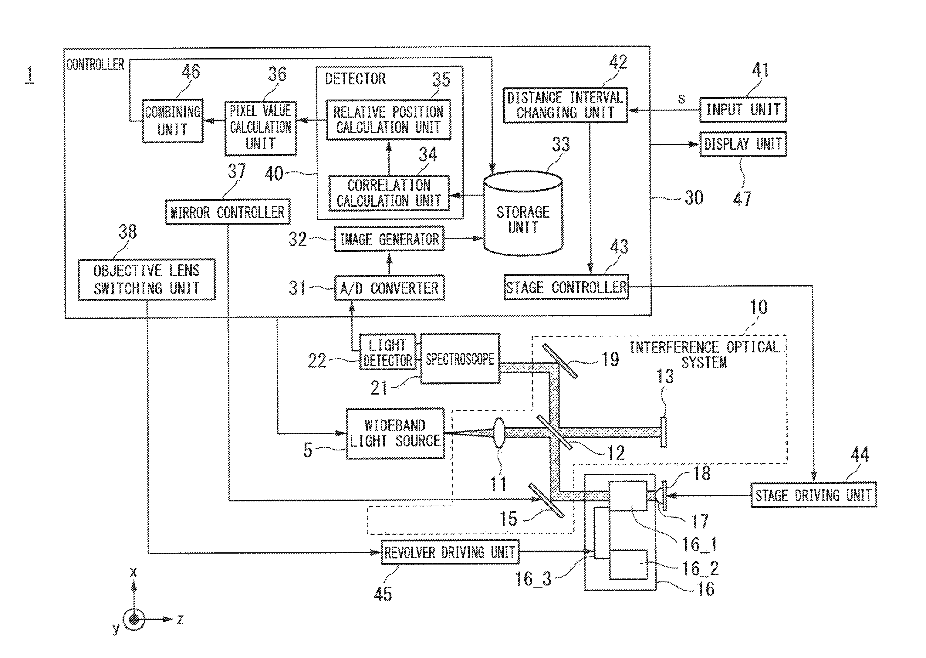
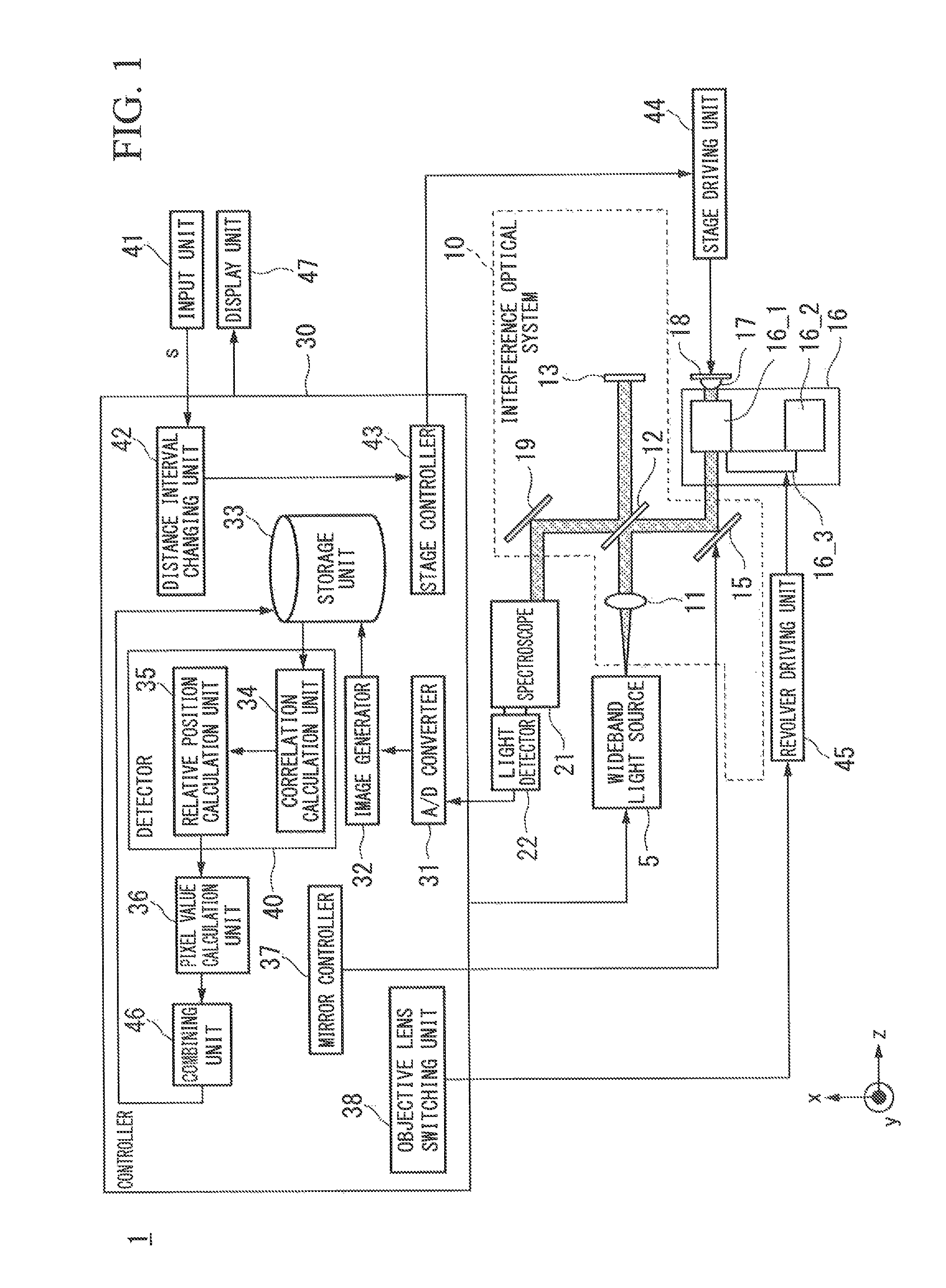
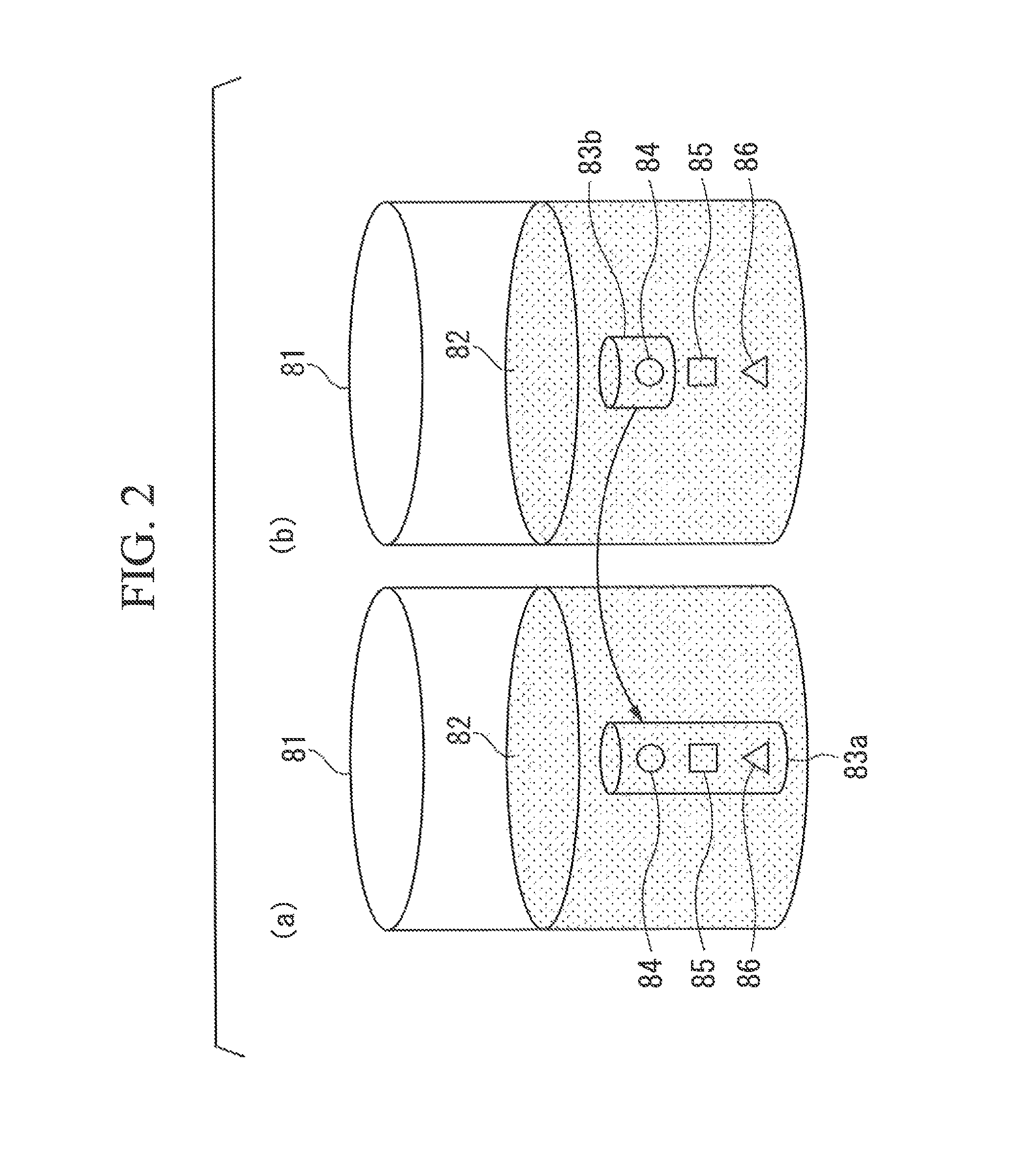
[0117]Subsequently, a second embodiment will be described. In the optical coherence tomography observation apparatus 1 of the first embodiment, the first tomographic image having the wide observation range is obtained by the first objective lens having the low NA, and the second tomographic image having the narrow observation range is obtained by the second objective lens having the high NA. Moreover, the optical coherence tomography observation apparatus 1 determines to which position in the first tomographic image the second tomographic image is allocated, and connects the second tomographic image, and thus, the tomographic image having the wide observation range in the depth direction and high definition is obtained.

[0118]An optical coherence tomography observation apparatus 1b in the second embodiment includes a diaphragm unit 14 (light control unit, switching unit, and selection unit) which reduces the illumination light, and the diaphragm unit 14 further reduces a light flux d...


PUM

PropertyMeasurementUnit
time domain methodaaaaaaaaaa
full width at half maximumaaaaaaaaaa
wavelengthaaaaaaaaaa

Abstract

An optical coherence tomography observation apparatus comprising a controller (30) and a detector (40), the controller being configured to illuminate first illumination light to an observation object, cause an image generator to generate a first tomographic image showing tomography of the observation object, illuminate second illumination light to the observation object, and cause the image generator to generate a second tomographic image showing tomography of the observation, and the detector being configured to detect a relative position of the second tomographic image with respect to the first tomographic image, at which a correlation of the second tomographic image with the first tomographic image becomes highest, are provided.

Description

CROSS-REFERENCE TO RELATED APPLICATION[0001]This is a Continuation application of International Application No. PCT / JP2012 / 057615, filed Mar. 23, 2012, which claims priority to Japanese Patent Application No. 2011-066744 filed on Mar. 24, 2011. The contents of the aforementioned applications are incorporated herein by reference.BACKGROUND[0002]1. Field of the Invention[0003]The present invention relates to an optical coherence tomography observation apparatus, a method for determining a relative position of images, and a program for determining the relative position of images.[0004]2. Description of Related Art[0005]Generally, in cell culture of the related art, cells which are two-dimensionally grown are observed, and the properties are evaluated. However, in order to express essential properties of the cells, the importance of growing the cells three-dimensionally has been becoming clear in recent years.[0006]With the above-described background, expectations with respect to a meth...

Claims


Application Information

Patent Timeline
Patent Type & Authority Patents(United States)
IPC IPC(8): G01B11/02G01B9/02G01N21/17G01N21/47
CPCG01B9/02091G01N21/4795G01B9/02044G01B9/02087G01N2021/1787
Inventor KAWANO, TAKESHINAKAYAMA, SHIGERU
Owner NIKON CORP
Why Eureka
Try Eureka