
Apparatus and method for imaging a subsurface using frequency-domain elastic reverse-time migration

a frequency-domain elastic and subsurface technology, applied in the field of subsurface exploration, can solve the problems of difficult to obtain a location for imaging, and the method has difficulty in imaging wide regions, and achieve the effect of efficient computing

Active Publication Date: 2015-02-10
SEOUL NAT UNIV R&DB FOUND
View PDF30 Cites 4 Cited by
  • Summary
  • Abstract
  • Description
  • Claims
  • Application Information

AI Technical Summary

Benefits of technology

This approach enables efficient computing and accurate investigation of complex topographical structures in elastic media by eliminating the need for computing partial derivative wavefields, resulting in improved subsurface imaging with reduced computational costs.

Problems solved by technology

However, since elastic medium has all of P, S and Rayleigh waves, it is not easy to obtain a location for imaging since undesired artifacts may be produced due to a correlation between the P, S and Rayleigh waves.
However, since the method is applied only to the time domain, and imaging of elastic medium requires a great deal of computer memory and computing time compared to acoustic medium, the method has difficulties in imaging wide regions.

Method used


Image

  • Apparatus and method for imaging a subsurface using frequency-domain elastic reverse-time migration
  • Apparatus and method for imaging a subsurface using frequency-domain elastic reverse-time migration
  • Apparatus and method for imaging a subsurface using frequency-domain elastic reverse-time migration

Examples


Embodiment Construction

[0026]The following description is provided to assist the reader in gaining a comprehensive understanding of the methods, apparatuses, and / or systems described herein. Accordingly, various changes, modifications, and equivalents of the methods, apparatuses, and / or systems described herein will be suggested to those of ordinary skill in the art. Also, descriptions of well-known functions and constructions may be omitted for increased clarity and conciseness.

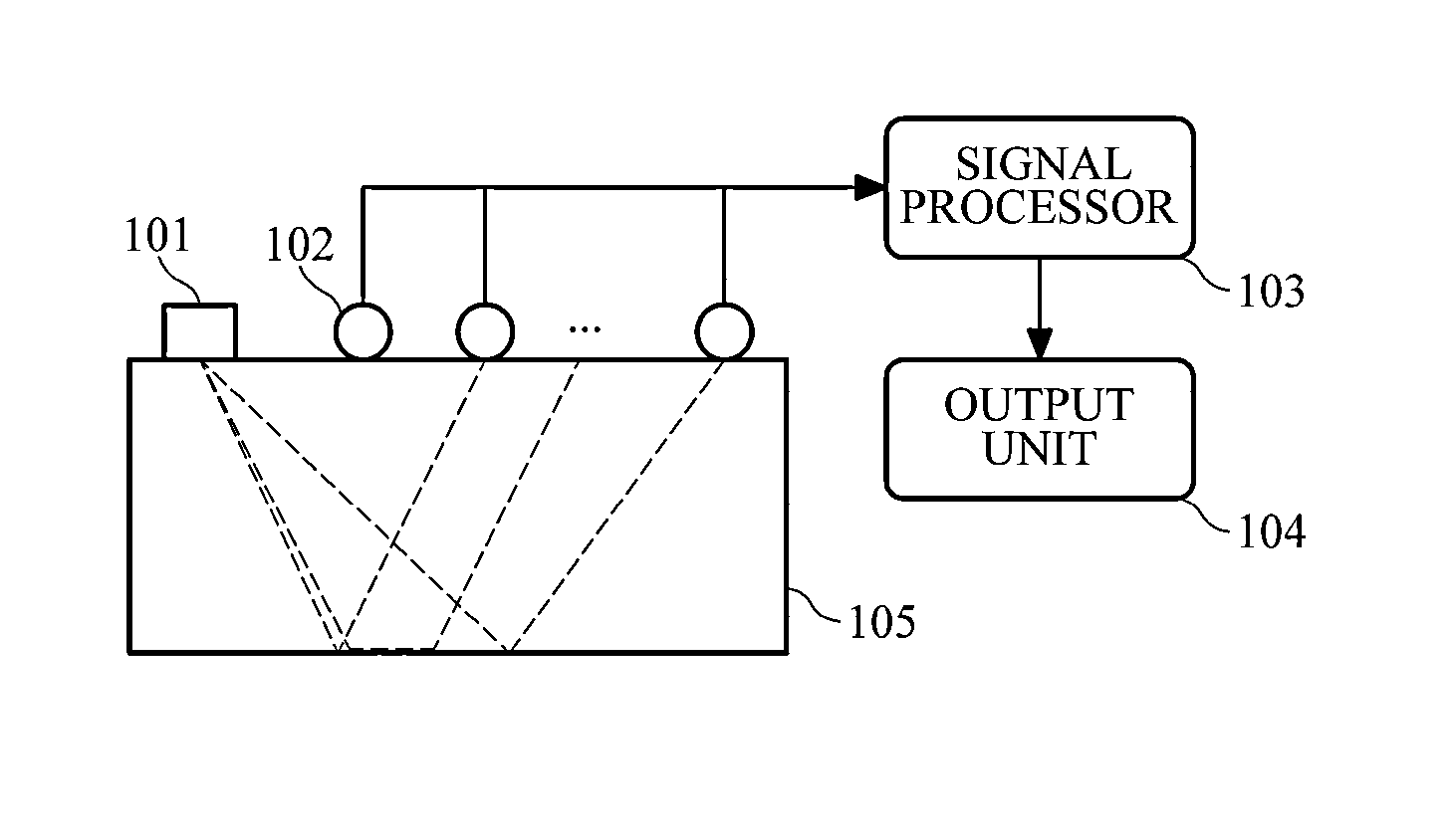
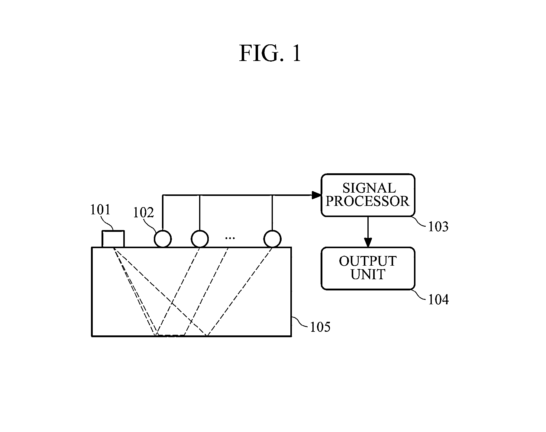
[0027]FIG. 1 is a diagram illustrating an example of a subsurface imaging apparatus using frequency-domain reverse-time migration in elastic medium. Referring to FIG. 1, the subsurface imaging apparatus may include a source 101, a receiver 102, a signal processor 103, and an output unit 104.

[0028]The source 101 is used to generate waves (source wavelets) toward a region 105 to be observed. The kind of the source 101 is not limited, and may be a dynamite, an electric vibrator, etc. The source 101 may use well-known waves or arbitra...


PUM


Abstract

Provided are an apparatus and method for imaging a subsurface using frequency-domain reverse-time migration in elastic medium. The subsurface imaging method represents a frequency-domain imaging condition as convolution of measured data and a partial derivative wavefield. That is, the subsurface imaging method applies a back-propagation algorithm to represent an imaging condition as convolution of a virtual source and a back-propagated wavefield. Then, the subsurface imaging method divides a virtual source vector and the back-propagated wavefield represented by a displacement vector into P- and S-wave potentials through Helmholtz decomposition, thereby providing a new imaging condition.

Description

CROSS-REFERENCE TO RELATED APPLICATION[0001]This application claims the benefit under 35 U.S.C. §119(a) of a Korean Patent Application No. 10-2010-0082160, filed on Aug. 24, 2010, the entire disclosure of which is incorporated herein by reference for all purposes.BACKGROUND[0002]1. Field[0003]The following description relates to subsurface exploration, and more particularly, to an apparatus and method for imaging a subsurface using frequency-domain elastic reverse-time migration.[0004]2. Description of the Related Art[0005]Subsurface exploration has been used to discover the subsurface and geological characteristics of a specific region, and particularly, to find natural resources such as oil buried in the subsurface. With an increase in use amount of underground resources, subsurface exploration has been widely performed on sea, as well as on the earth surface. Subsurface exploration on the earth or sea plays an important role in finding fossil fuel, such as natural gas or oil, whi...

Claims


Application Information

Patent Timeline
Patent Type & Authority Patents(United States)
IPC IPC(8): G01V1/28
CPCG01V1/28G01V2210/51G01V2210/67
Inventor SHIN, CHANGSOO
Owner SEOUL NAT UNIV R&DB FOUND
Learn More